Microcontroller Monitors Ionizers in Manufacturing Process
Members can download this article in PDF format.
What you'll learn:
- How to implement a microcontroller to monitor ac-motor speed.
- Steps taken to test and register the pulses detected for each motor.
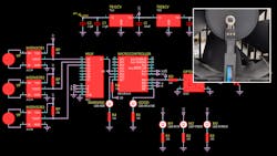
When you need to monitor the speed of ac motors to achieve high-quality manufacturing results, the microcontroller PIC16F1619 is a perfect solution for this task. The application of this design idea is for ionizer machines that require a reliable testing process of integrated circuits (Fig. 1).
A single failure of one fan motor might have high-cost losses in the production process. Thus, this microcontroller is crucial for ensuring high-quality production. In addition, the micro also performs self-diagnosis of the optocoupler to verify its operating status.
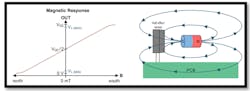
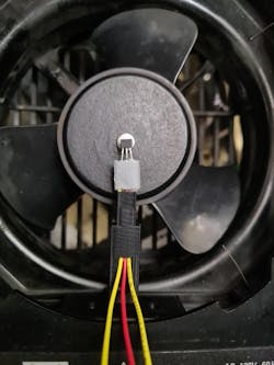
To detect the speed of each motor, we use a unipolar Hall-effect sensor A1104LUA-T (Fig. 2) that comes with an open drain configuration and requires a 10K pull-up resistor. This sensor delivers falling edge pulses indicating that the motor is rotating. The pulses are detected by TIMER3 in the PIC micro to compute the RPMs.
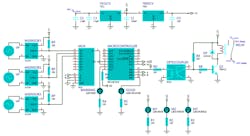
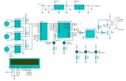
To test and register the pulses detected for each motor, an LCD display is connected to PORTC. Because all RPM measurements are taken in sequence, a multiplexer (CD4051) will select multiple ionizer motors. In addition, a self-diagnosis of the optocoupler is included to confirm the decisions taken in the output signal, making this design a robust system. Figure 3 shows the electronic schematic in testing mode and Figure 4 shows how the Hall-effect sensor is mounted on the ac motor.
The most important task for this circuit is to detect a stuck motor in high-cost ionizers. This function is part of a critical electrostatic-discharge (ESD) protection system. In this case, the micro indicates a warning signal when the speed is less than 700 RPM.
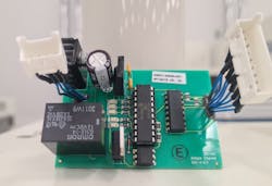
The resulting prototype PCB is assembled as shown in Figure 5.
In this design, the MCU will monitor the RPMs for three motors, which must be within the range of 700 to 2,800 RPM. Two LEDs on RC6 and RB7 will indicate the status of the circuit by detecting when the RD voltage status is wrong and whether the RPM is performing well. The self-diagnose system reads 2 conditional voltage values on RD of 0.75 V as maximum on the low state and 4 V as minimum on the high state.
In addition, the LED outputs RA4-M1, RA5-M2, and RC4-M3 will be turned on if one of the motors can’t reach at least 700 RPM. Each time the self-diagnose system or one of the ionizers doesn’t reach at least 700 RPM, PORTB.4 will be turned off, changing the relay to N.O. state (normally open) to indicate a warning signal:
        if VIN<818 then   ; Alarm sequence
            PORTB.4=0;    Activate the transistor
            FOR I=0 TO 4
                WARNING=0
                pause 500
                WARNING=1
                pause 500
            next i
        endif
Listing 1 (at the end of the article) shows the complete code written in the PBP3 compiler from melabs.com. The method to compute the RPMs with the PIC16F16F19 is as follows. A “for-next” cycle of 77 loops and a pause of 55 ms were set to give 4.23 seconds to each ionizer to reach 700 RPM. This speed can’t be reached by a user trying to trick the electronic system. The process is described in this part of the code:
; internal oscillator set to 4MHz.
    FOR I= 0 to 77;                   pulse train reading sequence
        T3CON.0 = 1;
        pause 55;
        TMR.byte0 = TMR3L;    LOW Register
        TMR.byte1 = TMR3H;   HIGH Register
        lcdout $FE,$C0,DEC TMR,"       "; Display pulses on LCD
    next I;
Using the internal oscillator at 4 MHz, we get each clock period TCY:
TCY = (4/FOSC), TCY = (4/4 MHz) = 1 µs
Reading loop = 77(55 ms + 6 µs); MCU takes 1 µs per instruction.
Reading loop = 4.2255 seconds.
To get the RPM, we use the formula:
Pulses per second = (Pulses/4.2355 s)
RPM = Pulses per second * 60
Therefore, we may reduce a step in the algorithm by multiplying a constant equal to 60/4.2355 s = 14.1661. This constant can be rounded off to 14; the RPM is obtained as indicated:
RPM = Pulses * (60/4.24)
Listing 1: Code for the Microcontroller PIC16F1619
  #CONFIG; FUSSES
    __config _CONFIG1,  _FOSC_INTOSC & _PWRTE_ON & _MCLRE_OFF & _CP_OFF & _BOREN_ON & _CLKOUTEN_OFF
    __config _CONFIG2,  _WRT_OFF & _PPS1WAY_OFF & _ZCD_OFF & _PLLEN_OFF & _STVREN_ON & _BORV_LO & _LVP_OFF
    __config _CONFIG3,  _WDTCPS_WDTCPS4 & _WDTE_ON & _WDTCWS_WDTCWS100 & _WDTCCS_LFINTOSC
  #ENDCONFIG
;CONFIGURATION OF THE INTERNAL CLOCK
OSCCON = %01101010;  Internal clock at 4MHz
OSCSTAT = %00011111; Enable internal clock
OSCTUNE = 0;                   Internal Osc works at calibrated frequency
;-------------------------------AD Configuration--------------------------------
ADCON0 = %00001101;  ADC Enabled
ADCON1 = %10000000;  Right justified
;---------------Enable PORTA and PORTB as digital outputs-----------------------
;--PORTA--
TRISA = 0;
ANSELA = 0;
OPTION_REG.7=0;
WPUA = 0;
;--PORTB--
TRISB = 0;
ANSELB = 0;
WPUB = 0;
LATB = 0
;--PORTC--
TRISC = %10100000;     RC7 and RC5 as input
ANSELC = %10000000; RC7 as analog
WPUC = 0;
LATC = 0;
;--Clear Ports--
PORTA = 0;
PORTB = 0;
PORTC = 0;
;//TIMER//
T3CON = %10000100; Enable timer 3 (T3CKL)
;-- LCD CONFIGURATION --
DEFINE LCD_DREG PORTC '      PORTC is LCD data port
DEFINE LCD_DBIT 0 '                  PORTC.0 is the data LSB
DEFINE LCD_RSREG PORTA'     RS is connected to PORTA.0
DEFINE LCD_RSBIT 0'                 RA0 as RS bit
DEFINE LCD_EREG PORTA '      E is connected to PORTA.1
DEFINE LCD_EBIT 1'                   RA1 as Enable bit
DEFINE LCD_BITS 4 '                 4 data line
DEFINE LCD_LINES 2 '               2-line display
DEFINE LCD_COMMANDUS 1500'  Use 1500uS command delay
DEFINE LCD_DATAUS 44 '      Use 44uS data delay
;--Define Variables--
i var byte
CH var byte
VD var byte[4]
VIN var word
ADC var word
REMAINDER var word
IN2 var byte
X var byte;
TMR var word;
PULSES var word
RPM var word
CLEAR
;-- ALIAS ---
WARNING var PORTC.6
GOOD var PORTB.7
M1 var PORTA.5
M2 var PORTA.4
M3 var PORTC.4
lcdout $FE,$80,"A.Chavez "
pause 1500
    lcdout $fe,$80,"PULSES X"
    lcdout $fe,$C0,"4.23 SEC "
    pause 1000;
;------------Clear Ports/Variables----------------------------------------------
        PORTB.4=0;
        GOOD=0;
        WARNING=0;
        M1=0
        M2=0
        M3=0
        vin=0
        ADC=0
        CH=9;      Analog channel (RC7)
;-------------Self-Diagnose voltage validation on low state---------------------
        gosub ADC_READ; Go to ADC sequence
        lcdout $FE,$C0,"V=",DEC VD[3],".",DEC VD[2],DEC VD[1],DEC VD[0]," "
        pause 1000
        gosub ADC_READ;     GO TO SEQUENCE
        lcdout $FE,$C0,"V=",DEC VD[3],".",DEC VD[2],DEC VD[1],DEC VD[0]," "
        pause 1000
        if VIN>153 then   ; Alarm signal sequence
            PORTB.4=0
            FOR I=0 TO 4
                WARNING=0
                pause 500
                WARNING=1
                pause 500
            next i
        endif
;--------------------------Set normal values------------------------------------
        PORTB.4=1 ;        Set HIGH normal state
        GOOD=1 ;            Set GOOD indicator ON
        WARNING=0;      Set warning indicator OFF
;-------------Self-Diagnose voltage validation on high state--------------------
    HERE:
        gosub ADC_READ;
        lcdout $FE,$C0,"V=",DEC VD[3],".",DEC VD[2],DEC VD[1],DEC VD[0]," "
        pause 1000
        if VIN<818 then   ; Alarm sequence
            PORTB.4=0
            FOR I=0 TO 4
                WARNING=0
                pause 500
                WARNING=1
                pause 500
            next i
        endif
;-----------------------------------MOTOR1--------------------------------------
        PORTB.4=1
        PORTB.5=0 ; MUX Selector 0
        PORTB.6=0
        pause 100
        lcdout $FE,$80,"PULSES  ";
        TMR3L = 0;
        TMR3H = 0;
    FOR i=0 to 77;         pulse train reading sequence
        T3CON.0 = 1
        pause 55
        TMR.byte0 = TMR3L; LOW Register
        TMR.byte1 = TMR3H; HIGH Register
        lcdout $FE,$C0,DEC TMR,"       "; Display pulses on LCD
    next i
    PULSES = TMR
    RPM = PULSES*14
    lcdout $FE,$80,"RPM"
    lcdout $FE,$C0,DEC RPM,"       ";     Show RPM current value on LCD
    pause 2000
;-------------------------Conditional Failure-----------------------------------
    IF RPM <= 700 THEN;    Conditional RPM
        PORTB.4=0;                 Set Low status and commute alarm
        WARNING=1;              Set on warning indicator
        GOOD=0;                     Set off GOOD indicator
        M1=1;                          Set on motor 1 indicator
        pause 100
        T3CON.0 = 0;              Disable TIMER3
        CH=9
        gosub ADC_READ;
        lcdout $FE,$C0,"V=",DEC VD[3],".",DEC VD[2],DEC VD[1],DEC VD[0]," "
        pause 1000
        if VIN>153 then   ; Alarm sequence
            PORTB.4=0
            FOR I=0 TO 4
                WARNING=0
                pause 500
                WARNING=1
                pause 500
            next i
        PORTB.4=1
        endif
        lcdout $FE,$80,"RPC"
        lcdout $FE,$C0,DEC TMR,"       " ; Pulses reached
        pause 3000
        TMR3L = 0;
        TMR3H = 0;
        ENABLE
    ENDIF
;-------------Self-Diagnose voltage validation on high state--------------------
        gosub ADC_READ;
        lcdout $FE,$C0,"V=",DEC VD[3],".",DEC VD[2],DEC VD[1],DEC VD[0]," "
        pause 1000
        if VIN<818 then   ; Alarm sequence
            PORTB.4=0
            FOR I=0 TO 4
                WARNING=0
                pause 500
                WARNING=1
                pause 500
            next i
        endif
;---Reset normal values---
    PORTB.4=1
    GOOD=1
    WARNING=0
    M1=0
    pause 100
;-----------------------------------MOTOR2--------------------------------------
    PORTB.5=1 ;MUX Selector 1
    PORTB.6=0
    pause 100
    lcdout $FE,$80,"PULSES  ";
    TMR3L = 0;
    TMR3H = 0;
    FOR i=0 to 77
        T3CON.0 = 1
        pause 55
        TMR.byte0 = TMR3L; LOW Register
        TMR.byte1 = TMR3H; HIGH Register
        lcdout $FE,$C0,DEC TMR,"       "
    next i
    PULSES = TMR
    RPM = PULSES*14
    lcdout $FE,$80,"RPM"
    lcdout $FE,$C0,DEC RPM,"       ";RPM
    PAUSE 2000
;-------------------------Conditional Failure-----------------------------------
    IF RPM <= 700 THEN    ;700RPM
        DISABLE
        PORTB.4=0
        WARNING=1
        GOOD=0
        M2=1
        pause 100
        T3CON.0 = 0
        CH=9
        gosub ADC_READ; GO TO SEQUENCE
        lcdout $FE,$C0,"V=",DEC VD[3],".",DEC VD[2],DEC VD[1],DEC VD[0]," "
        pause 1000
        if VIN>153 then  ;Indicator status alarm
            PORTB.4=0
            FOR I=0 TO 4
                WARNING=0
                pause 500
                WARNING=1
                pause 500
            next i
        PORTB.4=1
        endif
        lcdout $FE,$80,"RPC"
        lcdout $FE,$C0,DEC TMR,"       "
        pause 3000
        TMR3L = 0;
        TMR3H = 0;
        ENABLE
    ENDIF
;-------------Self-Diagnose voltage validation on high state--------------------
        gosub ADC_READ;
        lcdout $FE,$C0,"V=",DEC VD[3],".",DEC VD[2],DEC VD[1],DEC VD[0]," "
        pause 1000
        if VIN<818 then   ; Alarm sequence
            PORTB.4=0
            FOR I=0 TO 4
                WARNING=0
                pause 500
                WARNING=1
                pause 500
            next i
        endif
;---Reset normal values---
    PORTB.4=1
    GOOD=1
    WARNING=0
    M2=0
    pause 100
;-----------------------------------MOTOR3--------------------------------------
    PORTB.5=0 ;    MUX Selector 2
    PORTB.6=1
    pause 100
    lcdout $FE,$80,"PULSES  ";
    TMR3L = 0;
    TMR3H = 0;
    FOR i=0 to 77
        T3CON.0 = 1
        pause 55
        TMR.byte0 = TMR3L; LOW Register
        TMR.byte1 = TMR3H; HIGH Register
        lcdout $FE,$C0,DEC TMR,"       "
    next i
    PULSES = TMR
    RPM = PULSES*14
    lcdout $FE,$80,"RPM"
    lcdout $FE,$C0,DEC RPM,"       ";RPM
    pause 2000
;-------------------------Conditional Failure-------------------------
    IF RPM <= 700 THEN;    less than 700 RPM?
        DISABLE
        PORTB.4=0
        GOOD=0
        WARNING=1
        M3=1
        pause 100
        T3CON.0 = 0
        CH=9
        gosub ADC_READ; Go to ADC sequence
        lcdout $FE,$C0,"V=",DEC VD[3],".",DEC VD[2],DEC VD[1],DEC VD[0]," "
        pause 1000
        if VIN>153 then  ;Indicator status alarm
            PORTB.4=0
            FOR I=0 TO 4
                WARNING=0
                pause 500
                WARNING=1
                pause 500
            next i
        PORTB.4=1
        endif
        lcdout $FE,$80,"RPC"
        lcdout $FE,$C0,DEC TMR,"       "
        pause 3000
        TMR3L = 0;
        TMR3H = 0;
        ENABLE
    ENDIF
;---Reset normal values---
    PORTB.4=1
    GOOD=1
    WARNING=0
    M3=0
    pause 100
goto HERE
;-------------------------------------------------------------------------------
ADC_READ:
CH = CH<<2;
ADCON0 = CH^%10000001; Bitwise XNOR
pause 1
ADCON0.1 = 1;
HERE_ADC: IF ADCON0.1 = 1 THEN HERE_ADC; Stay here while conversion is ready
ADCON0.0 = 0;
ADC.byte0 = ADRESL;  Save low ADC register in ADC variable
ADC.byte1 = ADRESH; Save hig ADC register in ADC variable
DISABLE
REMAINDER = ADC*4887; Multiplying by RESLSB = 4.8887
VIN = div32 1000; Perform 16-BITS division
ENABLE
FOR X = 0 TO 3
    VD[X] = VIN DIG X
NEXT X
Return
End
Ricardo Jimenez holds a Master’s degree in Electronics from TecNM, campus Mexicali. Arturo A. Chavez received an Electronics Engineering degree from TecNM, campus Mexicali.
About the Author
Ricardo Jimenez
Ricardo Jimenez holds a master's degree in electronics from the Instituto Tecnologico de Mexicali.
Comment About the Article
To join the conversation, and become an exclusive member of Electronic Design, create an account today!

Leaders relevant to this article: