Microcontroller Performs Multiple Instrumentation Measurements
Members can download this article in PDF format.
What you'll learn:
- How to use the venerable PIC16F886 MCU to create a multifunction measurement device.
- What instrument measurements can this 6-in-1 device replicate?
When you need a versatile, multifunctional instrument for measuring six different types of parameters in the lab, the venerable microcontroller PIC16F886 is a suitable solution to perform such a task. The microcontroller in this design idea can perform the following instrument functions: voltmeter, thermometer, pulse counter, frequency counter, period meter, and tachometer.
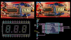
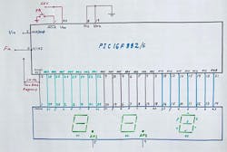
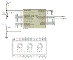
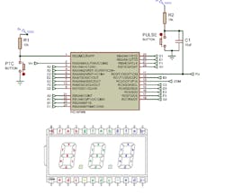
This design requires only a three-digit numerical LCD; its total current consumption is less than 1 mA. To drive the LCD, the microcontroller’s pulse-width modulator (PWM) generates a signal to drive the common input on the LCD. The PIC drives the LCD by inverting the data on its ports with respect to the common input. Figure 1 shows the electronic schematic for this design and Figure 2 shows the numerical 24-pin LCD display schematic.
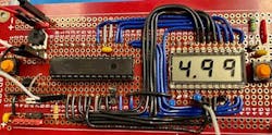
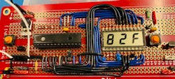
The assembled prototype board is presented in Figure 3. The voltmeter function is called Lb1. Figure 4 shows the thermometer function, dubbed Lb2.
To select the measurement functions (Lb1 through Lb6), you have to press the pushbutton PTC assigned to input RE3. The PIC micro starts with Lb1 by default (Fig. 5). You will see the message “Lb1” on the display, which corresponds to the dc voltmeter. To change to another instrument, press the pushbutton again. You will see each the “LbX” message in sequence.
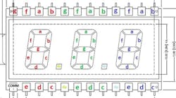
To turn off the decimal points on the display (pins 5 and 9), connect them to the common (pin 1) on the LCD. To activate a decimal point, connect it to 5 V with a 100k resistor.
Voltmeter (Lb1)
The PIC micro starts by default with Lb1, which is a dc voltmeter (Fig. 6). The voltage under measurement must be within the range of 0 to 5 V, and it’s applied to RA0 configured as an analog input (pin 2). Its resolution is 10 mV. You can increase the input voltage range up to 49.9 V by applying a voltage division network using two precision resistors, such as 180k and 20k.
Thermometer (Lb2)
In this configuration, you need a temperature sensor such as the LM34DZ or LM35DZ for Fahrenheit or Celsius degrees, respectively (Fig. 7). By pressing PB2 on RC0, you can select which sensor you’re using.
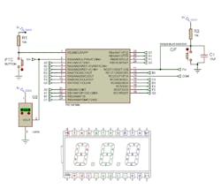
The PIC measures the temperature applied on the analog channel RA0/AN0. The temperature reading will be within the range of 0 to 250˚F with a resolution of 1˚F degree. For Celsius scale, the temperature is within the range of 0 to 120˚C.
3-Digit Counter (Lb3)
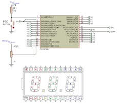
In this configuration (Fig. 8), the microcontroller captures the pulses applied to TIMER1 on the clock input (T1CKI) to make a three-digit counter. The pulses must be applied to the Timer1 Clock Input (T1CKI). When the counter reaches 1,000 counts, it’s cleared to start a new counting cycle. The 0.01-µF capacitor in series with resistor R2 is used to debounce the pushbutton and get clean pulses.
Frequency Counter (Lb4)
In this configuration, an input frequency sample is read by TIMER1 on RC0/T1CKI every 1.00 seconds. This configuration can measure frequencies within the range of 0 to 999 Hz with a resolution of 1 Hz (Fig. 9).
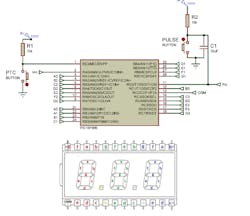
If the frequency is higher than 999 Hz, it stops TIMER1 and clears the counter to start a new frequency measurement cycle. You can change the code to measure up to 9.99 kHz by reducing its respective pause from 1.00 s to 100 ms (this instruction is bolded in Listing 2). In that case, its resolution would be equal to 10 Hz.
Period Measurement (Lb5)
To measure an input signal period applied to RA0, a 1000-Hz time-base frequency must be applied to TIMER1 by the internal PWM (CCP1). Thus, a jumper needs to be placed from the CCP1 output (pin 13) to the 16-bit T1CKI clock input (pin 11). Figure 10 shows its configuration.
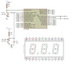
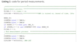
When a rising-edge input signal arrives to RA0, it starts measuring its period. When the signal goes to low logic, it stops the counting, and the period is displayed in milliseconds. With this code, the PIC can measure periods within the range of 1 to 999 ms, with a resolution of 1 ms.
The code for measuring a period consists of reading the logic status of RA0. The variable counter keeps updating its contents while RA0 stays high. Once it goes to low logic, the TIMER is disabled with the instruction T1CON.0. This is described in Listing 1.
Tachometer (Lb6)
In this case, the microcontroller works as a tachometer to display measurements within the range of 0 to 999 RPM, with a resolution of 1 RPM (Fig. 10, again). When the reading is higher than 999 RPM, the counters are cleared to start a new measurement cycle.
The PWM module delivers a 1000-Hz time base that’s used to measure the input signal period T, and then compute its equivalent in RPM by using the formula RPM = 6000/T. The method used here determines how many times the period reading in the counter fits into a loop of 60,000 counts, as follows:
 FOR X = 0 TO 60000 STEP COUNTER; determine RPM from period stored in variable counter.
RPM = RPM + 1; NEXT X;
This method is more accurate than performing a division because it doesn’t generate fractions.
Listing 2 below shows the complete code for the six instruments contained in the PIC16F883. The code is based on the compiler PBP3 from melabs.com.
Ricardo Jimenez holds a master’s degree in Electronics from TecNM/ITM campus Mexicali. Gabriel Lee Alvarez is pursuing his master’s degree in Computer Science from TecNM, campus Mexicali. Angel Dominguez holds a technical degree in Low Voltage Systems from Imperial Valley College, Imperial, Calif.
Listing 2: Code for the Six-Labs-in-One PIC Microcontroller
'*  Name    : 72segments-JANUARY26-22 version3.BAS
'*  Author  : R. Jimenez, M. Sc., and Gabriel Lee Alvarez
'*  Notice  : PB on RE3 requires 5.1K and 0.01 uF Cap for debouncing PB
'*  Date    : 5/18/2021,  8/01/21, 1/25/22
'*  Version : LAB5 requires external Time Base Freq and FF 74HC74
'*  Notes   : pic16f883 with 3-Digit Numerical LCD
'*          : 6 Labs in a single PIC 16F883
;Code consumes 1391 words out of 4091 available on 16F883
  #CONFIG ; configuration word
    __config _CONFIG1, _INTRC_OSC_NOCLKOUT & _WDT_OFF & _MCLRE_OFF & _LVP_OFF & _CP_OFF
  #ENDCONFIG
OSCCON = %01100111; $67  4-MHz internal oscillator
;-----------------
TRISA= %00000001: ANSEL= %00000001; RA0/AN0 is analog input
TRISB= %00000000: ANSELH= 0;        PORT B digital Output
TRISC= %00000001;                   PORTC digital Output. RC0 input
TRISE = %00001000;                  RE3/MCLr input
;-----------------
;DEFINE ADC_BITS 8;                  A-to-D converter set to 8 bits resolution
;DEFINE ADC_CLOCK 3;                 internal clock source 3 for the A/D converter
;DEFINE SAMPLEUS 50;                 wait 50 uS to settle down after 20 uS reading
ADCON0 = %00000001;
ADCON1 = %10000000;
;-----------------
;calculated base frequency for practices 5 and 6, frequency = 1/((pr2+1)*4*(1/fosc)*(tmr2 prescale))
; the value of frequenci = 1/((249+1)*4*(1/4Mhz)*(4)) = 1000 = 1 khz
CCP1CON = %00000001; PWM off
T2CON = %00000001; TMR2 ON, PRESCALER 4
PR2 = 249;

CCP VAR WORD;
CCP = 500;
CCP1CON.4 = CCP.0;
CCP1CON.5 = CCP.1;
CCPR1L = CCP>>2
;///---
OPTION_REG = %10000111; ADFM=1, A/D right justified

;-----------------
A var byte;          decimals segments to display in XOR with RC2
B var byte;          Units segments to display in XOR with RC2
C var byte;          Hundredths segments in XOR with RC2
L var byte;          Stores value of Common phase signal for LCD

PRACTIC VAR BYTE;

volt var WORD;                      variable volt to store for voltage readings
v1 VAR WORD: v2 VAR WORD;           variables to store each digit
digit3 VAR BYTE: digit2 VAR BYTE
digit VAR BYTE ;
digi var byte;
pattern3 VAR BYTE: pattern2 VAR BYTE;  variables for 7-segment conversions
pattern VAR BYTE
REMANENTE VAR WORD
I VAR BYTE;
CO VAR BYTE;
COUNTER VAR WORD;
PRACTIC = 0;
RPM VAR WORD;
T VAR BYTE
X VAR WORD;
ref var word;


PB1 var PORTE.1 ;   push button PB1 assigned to RE1
;-----------------

MAIN:           ; ---------------
    GOTO SEL_P;   Select Lab Practice to perform
GOTO MAIN;

D:   ; BCD to 7 segments decoding
    lookup digit3,[$3F,$06,$5B,$4F,$66,$6D,$7D,$07,$7F,$67],pattern3;
    B= (pattern3); XOR of RC2 with segments to display in the volts digit
    if PORTC.2 = 1 THEN B= ~B; invert bit for phase purposes
    PORTB.1= B.0; a1  segment assigned to pin RB1
    PORTB.2= B.1; b1  segment assigned to RB2
    PORTB.3= B.2; c1
    PORTB.4= B.3; d1
    PORTB.5= B.4; e1
    PORTB.6= B.5; f1
    PORTB.7= B.6; g1
    lookup digit2,[$3F,$06,$5B,$4F,$66,$6D,$7D,$07,$7F,$67],pattern2;
    A= (pattern2) ;  XOR with RC2 for driving the decimals volt digit
    if PORTC.2 = 1 THEN A = ~a
    PORTA.1= A.0; a2
    PORTA.2= A.1; b2
    PORTA.3= A.2; c2
    PORTA.4= A.3; d2
    PORTA.5= A.4; e2
    PORTA.6= A.5; f2
    PORTA.7= A.6; g2
    lookup digit,[$3F,$06,$5B,$4F,$66,$6D,$7D,$07,$7F,$67,$71],pattern;
    C= (pattern); XOR RC2 with segments to display the hundredths volt
    if PORTC.2 = 1 THEN C = ~C
    PORTB.0= C.0; a3
    PORTC.1= C.1; b3
    PORTC.3= C.2; c3
    PORTC.4= C.3; d3
    PORTC.5= C.4; e3
    PORTC.6= C.5; f3
    PORTC.7= C.6; g3
  RETURN
END;


ADC_READ:     ;     reading A/D conversion
       ADCON0.1 = 1; START CONVERSION
HERE: IF ADCON0.1 = 1 THEN HERE;
      VOLT.BYTE0 = ADRESL;
      VOLT.BYTE1 = ADRESH;
      REMANENTE = VOLT * 4887;
      VOLT = DIV32 1000;
RETURN

DEC_D:
    digit3 = VOLT DIG 3;                getting units value of v1 and store it in digit3
    digit2 = VOLT DIG 2;                getting decimals value of v1 and store it in digit2
    digit =  VOLT  DIG 1;                getting 1/100 value of v1 and store it in digit1
RETURN

SHOW_D:

FOR I = 1 to 20;                  20 loops to take a Reading every 400 mS,(20 Ms) = 0.4s
    PORTC.2 = 1;                       driving LCD  Common pin (phase signal) to logic H
    GOSUB D;                           invoking method D to drive the LCD display
    PAUSE 10;                    10 mS delay required by the LCD's Common pin
    PORTC.2= 0;                 common pin phase signal goes Low for 10 mS
    GOSUB D;                     invoking subroutine D to drive the LCD display
    PAUSE 10;                    10 mS to drive Common pin phase to logic L
NEXT I;                          I< 200? Continue loop, otherwise perform next instructio
RETURN

SEL_P:      ;           user selects Lab Practice
    PRACTIC= PRACTIC + 1;
    IF PRACTIC > 6 THEN PRACTIC = 1; MAX PRACTICES IS 6 on THIS chip
    PAUSE 200

    SELECT CASE PRACTIC
    CASE 1
        GOTO LB_1
    CASE 2
        GOTO LB_2
    CASE 3
        GOTO LB_3
    CASE 4
        GOTO LB_4
    CASE 5
        GOTO LB_5
    CASE 6
        GOTO LB_6
    END SELECT
GOTO MAIN;

;*-*-*-*-*-*-*-*-*-*-*-*-*-*-*-*-*-*-*-*-*-*-*-*-
LB_1:           ;  LAB1 VOLTMETER
    TRISA= %00000001: ANSEL= %00000001; RA0/AN0 configured as analog input
    co = 1;
    FOR i  = 1 to 60
       GOSUB MESSAGE
       pause 20;
    next i

LB_1_HERE:
      GOSUB ADC_READ;
      GOSUB DEC_D;
      GOSUB SHOW_D;
      IF PORTE.3 = 0 THEN goto SEL_P;
      GOTO LB_1_HERE;
RETURN
;*-*-*-*-*-*-*-*--*-*-*-*-*-*-*-*-*-*--*-*-*-*-*-

LB_2:     ; Lab 2 Thermometer in Fahrenheit degrees with LM34Z sensor
    co = 2;
    FOR i  = 1 to 60
       GOSUB MESSAGE
       pause 20;
    next i

LB_2_HERE:
      GOSUB ADC_READ;
      ;GOSUB DEC_D;
      if VOLT < 1000 THEN
        digit3 = VOLT DIG 2;                getting units value of v1 and store it in digit3
        digit2 = VOLT DIG 1;                getting decimals value of v1 and store it in digit2
        digit =  10;                getting 1/100 value of v1 and store it in digit1
      else
        gosub DEC_D
      endif
      GOSUB SHOW_D;
      IF PORTE.3 = 0 THEN goto SEL_P;
      GOTO LB_2_HERE;

GOTO MAIN;
;-*-*-*-*-*-*-*-*-*-*-*-*-*-*-*-*-*-*-*--*-*-*-*-

LB_3:  ;LAB 3 Decimal Counter with TIMER1 clocked by external pulses
    co = 3;
    FOR i  = 1 to 60
       GOSUB MESSAGE
       pause 20;
    next i
    T1CON = %00000111;;TIMER ENABLED
LB_3_HERE:
      ;----------------
      ;TMR1H = 0;
      ;TMR1L = 0;
      ;PAUSE 1000;
      COUNTER.BYTE0 = TMR1L;
      COUNTER.BYTE1 = TMR1H
      IF COUNTER> 999 THEN
        COUNTER = 0;
        TMR1H = 0;
        TMR1L = 0;
      ENDIF
      VOLT = COUNTER*10;
      GOSUB DEC_D;
      GOSUB SHOW_D;
      IF PORTE.3 = 0 THEN goto SEL_P;
      GOTO LB_3_HERE;

GOTO MAIN;
;-*-*-*-*-*-*-*-*-*-*-*-*-*-*-*-*-*-*-*--*-*-*-*-
;*-*-*-*-*-*-*-*--*-*-*-*-*-*-*-*-*-*--*-*-*-*-*-

LB_4:            ; Frequency counter
    co = 4;
    FOR i  = 1 to 60
       GOSUB MESSAGE
       pause 20;
    next i
    T1CON = %00000111;;TIMER ENABLED
LB_4_HERE:  ;         Frequency Counter 0-999 Hz
      ;----------------
      TMR1H = 0;
      TMR1L = 0;
      PAUSE 1000;     take a sample reading for 1.00 Sec
      COUNTER.BYTE0 = TMR1L;
      COUNTER.BYTE1 = TMR1H
      IF COUNTER> 999 THEN    ; overflow? clear TMR1
        COUNTER = 0;
        TMR1H = 0;
        TMR1L = 0;
      ENDIF
      VOLT = COUNTER*10;
      GOSUB DEC_D;
      GOSUB SHOW_D;
      IF PORTE.3 = 0 THEN goto SEL_P;
      GOTO LB_4_HERE;

GOTO MAIN;
;-*-*-*-*-*-*-*-*-*-*-*-*-*-*-*-*-*-*-*--*-*-*-*-
;HPWM 1,127,1000

LB_5:               ;PERIOD METER
    co = 5;           Practice 5
    FOR i  = 1 to 60
       GOSUB MESSAGE
       pause 20;
    next i
    T1CON = %00000110; TIMER1 disabled
    ANSEL = 0;
    T2CON.2 = 1;    TIMER2 enabled?


LB_5_HERE: ;     PERIOD METER, BASE FREQUENCY taken internally at 1k Hz
      ;--------- from PWM, change it to an external time base applied
      ;           to TMR1L and TMR1H to ge 10 bits for the display
      ;          the signal to be measured is connected to ra0
      TMR1H = 0;
      TMR1L = 0;
      PAUSE 1000;

      GOSUB SHOW_D;
      HERE_51:
        ;this section is used to refresh the lcd in idle state
        if TMR0 => 240 THEN
                T = T+1;
                TMR0 = 0;
           ENDIF
        IF T > 100 THEN
             GOSUB SHOW_D;
             T = 0;
        ENDIF


      ;PORTC.2 = ~PORTC.2
      IF PORTE.3 = 0 THEN goto SEL_P;
      if PORTA.0 = 0 THEN HERE_51
      ;*************************************************************************
;     measurement process ******************************************************
      T1CON.0 = 1; timer 1 on
      CCP1CON = %00001111;***************PWM is turned on, based of time, 1khz

      HERE_52:
      COUNTER.BYTE0 = TMR1L;
      COUNTER.BYTE1 = TMR1H
      IF PORTE.3 = 0 THEN goto SEL_P;
      if (PORTA.0 = 1) and COUNTER=<999 THEN HERE_52
      T1CON.0 = 0;
      ; End measurement process  ********************
      ;*******************************************
      COUNTER.BYTE0 = TMR1L;
      COUNTER.BYTE1 = TMR1H
      CCP1CON = %00000001; PWM OFF
      IF COUNTER > 999 THEN
        VOLT = 9990;
        GOSUB DEC_D;
        GOSUB SHOW_D;
        VOLT = 0;
        GOSUB DEC_D;
        GOSUB SHOW_D;
                VOLT = 9990;
        GOSUB DEC_D;
        GOSUB SHOW_D;
        VOLT = 0;
        GOSUB DEC_D;
        GOSUB SHOW_D;
      ELSE
        VOLT = COUNTER*10;
        GOSUB DEC_D;
        GOSUB SHOW_D;
      ENDIF
      IF PORTE.3 = 0 THEN goto SEL_P;
      GOTO LB_5_HERE;

GOTO MAIN;
;-*-*-*-*-*-*-*-*-*-*-*-*-*-*-*-*-*-*-*--*-*-*-*-

LB_6:          ; TACHOMETER
    co = 6;
    FOR i  = 1 to 60
       GOSUB MESSAGE
       pause 20;
    next i
    T1CON = %00000110;;TIMER ENABLED
    ANSEL = 0;
    T2CON.2 = 1;


LB_6_HERE:      ; TACHOMETER 1-999 RPM
      ;----------------
      TMR1H = 0;
      TMR1L = 0;
      PAUSE 1000;

      GOSUB SHOW_D;
      HERE_61:
      ;this section is used to refresh the lcd in idle state
           if TMR0 => 240 THEN
                T = T+1;
                TMR0 = 0;
           ENDIF
        IF T > 100 THEN
             GOSUB SHOW_D;
             T = 0;
        ENDIF

      IF PORTE.3 = 0 THEN goto SEL_P;
      if PORTA.0 = 0 THEN HERE_61
      ;*********************************
      ; measurement process **************

      T1CON.0 = 1; tmr1 on
      CCP1CON = %00001111; pwm on, 1 khz

      RPM = 0; clear rpm
      HERE_62:
      COUNTER.BYTE0 = TMR1L;
      COUNTER.BYTE1 = TMR1H

      IF PORTE.3 = 0 THEN goto SEL_P;
      if (PORTA.0 = 1)  THEN HERE_62;

      T1CON.0 = 0;
      ; End measurement process  *******
      ;******************************
      COUNTER.BYTE0 = TMR1L;
      COUNTER.BYTE1 = TMR1H
      CCP1CON = %00000001; pwm off
       if COUNTER = 0 THEN LB_6_HERE

       FOR X = 0 TO 60000 STEP COUNTER; obtain RPM from period
            RPM  = RPM + 1;
       NEXT X;


       IF RPM > 999 then
        VOLT = 9990;
        GOSUB DEC_D;
        GOSUB SHOW_D;
        VOLT = 0;
        GOSUB DEC_D;
        GOSUB SHOW_D;
                VOLT = 9990;
        GOSUB DEC_D;
        GOSUB SHOW_D;
        VOLT = 0;
        GOSUB DEC_D;
        GOSUB SHOW_D;
      ELSE
        VOLT = RPM*10;
        GOSUB DEC_D;
        GOSUB SHOW_D;
      ENDIF

      IF PORTE.3 = 0 THEN goto SEL_P;
      GOTO LB_6_HERE;

GOTO MAIN;
;-*-*-*-*-*-*-*-*-*-*-*-*-*-*-*-*-*-*-*--*-*-*-*-

MESSAGE:
    B= ($38); XOR of RC2 with segments to display in the volts digit
    if PORTC.2 = 1 THEN B = ~B
    PORTB.1= B.0; a1 segment assigned to pin RB1
    PORTB.2= B.1; b1  segment assigned to RB2
    PORTB.3= B.2; c1
    PORTB.4= B.3; d1
    PORTB.5= B.4; e1
    PORTB.6= B.5; f1
    PORTB.7= B.6; g1
    A= ($7C);  XOR with RC2 for driving the decimals volt digit
    if PORTC.2 = 1 THEN A = ~A
    PORTA.1= A.0; a2
    PORTA.2= A.1; b2
    PORTA.3= A.2; c2
    PORTA.4= A.3; d2
    PORTA.5= A.4; e2
    PORTA.6= A.5; f2
    PORTA.7= A.6; g2
    lookup CO,[$3F,$06,$5B,$4F,$66,$6D,$7D,$07,$7F,$67],pattern;
    C= (pattern); XOR RC2 with segments to display the hundredths volt
    if PORTC.2 = 1 THEN C = ~C
    PORTB.0= C.0; a3
    PORTC.1= C.1; b3
    PORTC.3= C.2; c3
    PORTC.4= C.3; d3
    PORTC.5= C.4; e3
    PORTC.6= C.5; f3
    PORTC.7= c.6;     Decimal Point ON, using a bitwise NOT function

RETURN
end
About the Author
Ricardo Jimenez
Ricardo Jimenez holds a master's degree in electronics from the Instituto Tecnologico de Mexicali.
Comment About the Article
To join the conversation, and become an exclusive member of Electronic Design, create an account today!

Leaders relevant to this article: