First-Time FPGA Success Requires Exhaustive Examination of Clock Domain Crossings

The checkbox is the enemy of a successful ASIC tapeout or FPGA/system release into production. This is counter-intuitive, as the checklist is critical in ensuring that process is followed and that nothing is forgotten or overlooked. All projects should have a good checklist and all good projects have a great one. However, the reality is that checklists alone imbue a false sense of security by shifting the focus from how something was done to if something was done. The details are lost.
The “CDC Verification Complete” entry in the checklist is one such example of being necessary but not sufficient.
Clock Issues Contribute to a Significant and Increasing Number of System Failures
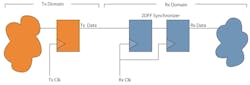
Clocking issues often have to deal with data corruption or signal loss across the boundary between two asynchronous clock domains, known as a clock domain crossing (CDC). As data or control signals transit from one clock domain to another (Fig. 1), those signals have timing characteristics relative to the transmitting clock domain. These signals are eventually sampled in the receiving domain by a clocked element, such as a flip-flop. A flip-flop whose data input changes too closely to the clock edge will enter a transitional, indeterminate state whose duration is probabilistic. This is known as a metastable state.
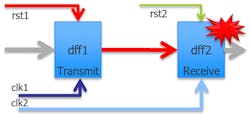
Many clock-boundary synchronization schemes exist to ensure that control or data signals are transferred accurately despite this metastable behavior. Without such a mechanism, incorrect values on the data or control signals will be sampled and erroneous behavior will result.
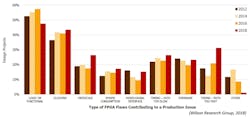
These clocking issues are more prevalent than ever in FPGA-based system products heading into the lab or, even more importantly, the market. According to the 2018 Wilson Research Group Functional Verification Study, clocking flaws are the second-leading cause of production issues in FPGAs, up almost 20% in the last six years, and are on pace to become the leading cause of FPGA production issues (Fig. 2).
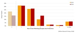
Further, the same Wilson Research Group study identified that in 2018, 84% of FPGA designs had non-trivial bugs escape into production (Fig. 3). In the FPGA space, there’s a clear need for more verification in general, including more CDC verification.
But it’s important to first understand what’s causing the escalating trend of clocking errors escaping into production. Otherwise an increase in effort may not address this trend.
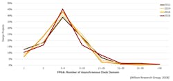
We’re all aware that designs are always growing in size and complexity. This results in either an increase in the number of clocks or the number of control and data signals crossing the clock domain boundaries—or both. As seen in Figure 4, the number of clocks in FPGAs has remained pretty much the same, perhaps slightly increasing, during the last six years. Since the number of clocks isn’t substantially increasing, the rising trend in flaws must be due to increased complexity and the number of data and control signals transitioning between clock domains. In other words, there are more CDCs.
What’s needed is not just greater use of CDC verification, but also an increase in adoption of more comprehensive CDC verification methodologies. Such methods should provide an exhaustive analysis based on a complete understanding of all of the potential failure modes for CDC.
Common, Simple Means to Manage Clock Domain Crossings
The issues with metastable behavior in designs are well-understood. Most FPGA teams have a methodology to deal with such issues. These methods include adding synchronization mechanisms where these crossings exist (and potentially utilizing a library of pre-approved and reviewed synchronizers), followed by design reviews to ensure that all CDCs are appropriately synchronized. FPGA vendor tool suites are able to perform a clock analysis on the netlist and identify potential CDCs, leaving the team to decide if the CDCs are or are not correctly designed.
If this isn’t considered sufficient, teams may rely on simulation to further identify any clocking issues. Clocks may be modeled as asynchronous and the flip-flops in the design may be made sensitive to timing violations such that they generate an unknown output, or “X,” during the time of the metastable behavior. In this manner, the team follows a CDC verification methodology that uses proscribed synchronizers to appropriately transition signals across the CDCs, reviews the identified crossings in the tool reports, and then relies on simulation to confirm them.
Many teams end their analysis here. Yet why is the increasing trend of clocking issues in production so prevalent? Answer: This level of CDC analysis and verification is insufficient.
Limitations of Reviews
Designers typically feel their code is bug-free until a bug is found in it. The same is true for CDC issues. It’s very common for teams to believe (and therefore wager their product’s market success on such a belief) that in knowing where their CDCs are, and by following simple rules, clocking issues cannot arise. Reviews are put in place as a cross-check. However, reviews are subject to human error, human limitations, and human assumptions. As such, reviews have limited effectiveness when it comes to functional issues that are common in today’s designs. Two such examples are protocol violations and reconvergence.
Protocol Violations
It’s not sufficient to simply identify that a synchronizer is located at every CDC. To ensure that the CDC operates correctly, the protocol required for the synchronization logic must be verified to be met under all conditions.
Consider a simple CDC/synchronization interface, such as a simple 2DFF synchronizer on a single control bit (Fig. 5). This type of design is typically found in a library of pre-approved and reviewed synchronizers. It’s also a synchronizer with an associated synchronization protocol—that the signal on the transmit side be held long enough to be sampled on the receive side. Reviews may suffice for this simple example, but as the protocols and schemes become more complex and parallel, human error becomes prevalent (Fig. 5, again).
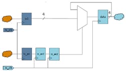
Consider a four-bit data bus. In such circumstances, well-known synchronization techniques, such as the D-Mux synchronizer shown in Figure 6, will cause the data to be correctly sampled on the receive side. This requires a different synchronization protocol—that, within the transmit domain, the data is valid before or at the same time as the valid signal and is held until after the valid signal is no longer active. This is still possible to verify in review, but it’s becoming more complex.
As power, performance, and congestion constraints demand much from the design, latency reductions move CDCs deeper into functionality and into parallel paths. For instance, it’s typical for the CDC to run through the middle of a FIFO and across parallel interfaces. A FIFO has a valid protocol (for instance, the FIFO is never written when full or read while empty) that must be verified. This type of CDC synchronization protocol is much more complex to verify by review.
Reconvergence Issues
A CDC may not be isolated to a single bit or single bus crossing between domains. Instead of running just one signal across a boundary, multiple signals may transit across a CDC. Furthermore, signals may be used not only in one receive domain, but also in multiple domains. Even more complex, the signals in both domains may be used in yet a third domain. In these scenarios, downstream logic on the receive side(s) will depend on the timing relationships to be maintained as they’re defined in the transmit domain. However, the CDC can create a functional bug due to unpredictable delays through the CDC synchronizers (Fig. 7).
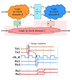
Figure 7 identifies a simple reconvergence scenario. It’s not difficult to imagine very complex reconvergence scenarios in which the signals that transit across a CDC aren’t actually consumed in the receive domain(s) until many cycles later. Regardless, in either scenario, human review of reconvergence is challenging at best, and very realistically error-prone and likely to miss issues.
Limitations of Simulation
Is functional simulation an acceptable analysis cross-check that the presence of synchronization on reviewed crossings is correct? The goal of such simulations is to identify when data is corrupted or signals are lost across the CDC. A team may encounter several challenges that can lead them to miss issues.
The first is that digital simulations, by definition, don’t handle non-digital behavior well. Thus, the metastable behavior of a flip-flop or other storage element isn’t modeled in traditional digital simulations. It can easily be either too pessimistic, injecting an unknown into the simulation that causes a cascade of Xs and unusable results, or too optimistic, missing an issue. As a result, verifying the correct synchronization against the metastable behavior is challenging.
Should a team conquer that issue successfully, it must next ensure that the constraints on the clocks precisely reflect the scenarios on the real clocks in silicon. Only by doing this will the simulations hit the scenario required to create and test CDCs properly. This isn’t easily done exhaustively. For complex designs, it may require more simulation cycles than the team can afford, in order to hit just the right scenario to cause the CDC violation. Constrained-random control of truly asynchronous clocks results in many combinations.
The final challenge has to do with the definition of a passing test. It’s possible that a functional test may not actually fail even though data corruption or signal loss occurs through a clock domain crossing. Even if the correct combination of clock constraints is enabled for a test, and the metastable behavior is appropriately modeled, the test must be sensitized in some manner to the path in question. Not all tests focus on all paths.
Borrowing CDC Techniques from the ASIC World
In summary, relying on reviews and functional simulation is at best a very challenging prospect, but at worst is error-prone and will cause a design team to miss key CDCs that exist in systems. Clearly, reviews and simulation aren’t enough. What’s needed instead is exhaustive, non-simulation-based verification of clock networks and CDCs.
Fortunately for FPGA and systems designers, the challenges of multiple-clock-domain designs are easily addressed by the robust and broad CDC solution spectrum available today and matured by the ASIC sector for nearly 20 years. These formal-verification-based features are readily applicable to the FPGA and system design space. These tools can easily analyze and identify issues where reviews and simulation fall short. Equally important, these solutions are run on the source code and not the synthesized netlist, identifying issues earlier in the design process when they can be fixed more efficiently and quickly.
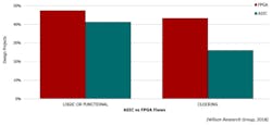
The success of the ASIC industry in adopting CDC verification can be seen in the different results between the ASIC community, where robust CDC use is common, and the FPGA community, where it’s less common. As seen in Figure 8, the Wilson Research Group 2018 survey identified clocking issues as being the root cause of a functional flaw in an ASIC only 26% of the time, compared to 43% of the time for FPGA designs.
FPGA designs go into production with a significant number of clocking issues. These issues can be found and addressed prior to production with increased adoption of CDC verification. Moreover, the quality of the CDC analysis is critical to ensuring that designs are clean as they head into deployment. Exhaustive analysis with formal-based tools is a highly effective means of improving results.
Chris Giles is a Product Marketing Manager for CDC and RDC tools at Mentor, a Siemens Business.
About the Author
Chris Giles
Product Marketing Manager, Mentor, a Siemens Business
Chris Giles is a Product Marketing Manager for CDC and RDC tools at Mentor, a Siemens Business. The author of multiple patents, Chris has led the design and verification of IP and SoCs for over 25 years across multiple industries and technologies.
Comment About the Article
To join the conversation, and become an exclusive member of Electronic Design, create an account today!

Leaders relevant to this article: