EMI Suppression Shields: Understanding the Basics
This article is part of the TechXchange: Delving into EMI, EMC and Noise
You may have heard of “EMI suppression” or “RF antenna” sheets, which are thin, flexible magnetic shields. Maybe they have been seen laying around the laboratory, typically black or gray in color, but sometimes they’re exotic and silver-looking and appear to have come off the mysterious aircraft that crashed in Roswell, New Mexico in 1947. You may have physically touched them, and/or maybe actually used them, but do we really know how they work or if the best material was used?
It all starts with magnetic materials. Those thin, flexible magnetic sheets are utilized in a variety of applications: to suppress unwanted EMI signals (for both radiated and susceptibility); for magnetic-field (H) shaping and directionality in NFC and RFID applications; to provide shielding and coil optimization in both magnetic induction and magnetic resonance wireless power applications; to lessen eddy-current losses of other resonance applications; to being used as an ESD protection device; and more.
Many suppliers have various materials documented by differing datasheets and data curves. But without a deep background in material science or vast experience, choosing the right material can become a challenge. Each application may have a different set of key parameters, e.g. which frequencies need to be attenuated or which frequencies need to have to the lowest losses?
Magnetic sheets come in metal powder-, ferrite-, polymer- and metallized-based materials with each supplier’s material being unique. Each supplier can also feature data of their materials’ strengths and target applications in a variety of ways, thus leaving the intended user, at times, with many questions.
Magnetic shields are considered by many as a “band-aid” for EMI suppression applications; that is, only used, maybe temporarily as a quick fix when all other solutions have been exhausted. The fact is, there are times when traditional solutions don’t work or would take too long to implement and that the “band-aid” may be the most cost-effective solution. There are also applications where magnetic shields must be used.
This article aims to help educate the reader and make the selection process easier and more efficient specifically for EMI suppression issues (due to limited space).
The Fundamentals Behind It
For EMI suppression (i.e. attenuating unwanted signals as compared to NFC/RFID applications where optimizing wanted signals and frequencies is key), the following equation can be used to help understand:
µ = µ’ – jµ” (1)
where µ’ is the material’s permeability (hence related to inductance) and µ” is related to the material’s losses (resistance) and is a result of frequency and phase shift at the grain level of the material. Over frequency, both of these parameters may (will) change, depending on the material.
For EMI suppression applications:
µ’ = higher yields lead to better shielding performance through H field containment or absorption
µ” = higher yields lead to better noise suppression/attenuation through material losses
Permeability defines the ability of a material to support the formation of a magnetic field within itself and contain magnetic flux. Therefore, containing more magnetic flux enables the higher µ’ material to keep more of the unwanted radiated magnetic field within the magnetic material and away from sensitive areas. When µ” is at higher values, a more resistive path is created for any magnetic field passing through the material, and it allows for the unwanted magnetic field noise to be absorbed and converted to heat. Each unique material composition, density and inner grain size and shape will impact both µ’ and µ”.
The quality factor (Q) of the material, a figure of merit that describes the potential to store energy relative to the loss within the material, is related to both µ’ and µ”and is given by:
Q = µ’/µ” (2)
For EMI suppression applications, one typically selects a low-Q material that’s lossy at the problem frequencies and thus increases the attenuation at those frequencies. This contrasts with NFC/RFID and other similar resonant low-power communication systems, where the emphasis is on increasing Q. Therefore, it’s critical to obtain the µ’, µ” curve to select the best material. Examples of material curves are shown in Figure 1.
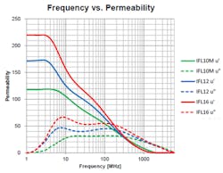
As can be seen from these sets of curves, the behavior of the materials goes from low loss, high Q at the 1 MHz range to high loss (µ”), low Q (hence high attenuation) starting in the 2- to 4-MHz range and continuing up to 2- to 3-GHz range. Usually, this broad spectrum of attenuation isn’t required; therefore, the user can focus on choosing the best material at each individual problem frequencies.
E & H Fields
Another key area are the impacts of the magnetic (H) and electric (E) field strengths. The magnetic field strength for an inductor (a common EMI generator in switch-mode power supplies—SMPS—and just one of many equations) is given as:
H ∝ N × 1 (3)
where N = the number of turns of the coil pattern used within the power magnetics, and I = current through the coil (A).
Typically, the number of turns within an inductor isn’t provided by suppliers, as is commonly done for transformers. Thus, the user doesn’t always know the true H field strength. For power applications that use higher currents, these create both stronger predictable H fields and stronger, potentially spurious H fields. In turn, it creates more magnetic flux (density given as “B” in a typical B-H curve) subjected upon the magnetic shield.
The stronger the magnetic field, the better the shielding needs to be. This can be achieved by either increasing µ’ in Equation 1 to contain more magnetic flux or by increasing the physical thickness of the magnetic shield. This relationship is given in the following figure of merit:
µ’ × t (4)
where µ’ = permeability and t = thickness of the magnetic sheet.
In Figure 1, the curve in red, labeled as IFL16, which has the highest attenuation, also possesses the highest permeability (µ’ = 220). This enables the material to better contain the flux energy. The performance impact of shield thickness is highlighted in Figures 2a and 2b.
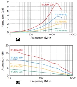
In Figures 2a and 2b, “-200,” “-100,” “-050,” and “-025” are the respective thicknesses in microns (µm) so that, for example, “-100” is 100-µm thickness. Additional thickness also means more magnetic material mass is present and can support higher levels of magnetic flux. In certain EMI suppression applications, attention needs to be paid to the magnetic-flux-density (Bs) value of the material. One must ensure that the magnetic material doesn’t saturate and lose its shielding effectiveness through diminished attenuation performance and thus allow some level of the noise energy to pass through.
For E fields, the electrical-field strength can be specified as:
E = F/Q = kQ/D2 = V/D (5)
where E = electric field (vector) strength (N/C); F = electric force (N); Q = volume of charge (C); k = electrostatic (coulomb) constant (8.99 x 10⁹ Nm2/C2); D = distance between charge source and point of reference (m); and V = voltage (V) across distance (D).
It’s then apparent that the higher the voltage, the stronger the electrical-field strength. One of the key applications for EMI suppression sheets is to reduce the voltage induced on other components in proximity to the voltage source.
Why two sets of attenuation curves in Figures 2a and 2b? In applications where one is trying to suppress (protect) noise being generated from traces on a PCB, FPC, ribbon cable, or other signal path medium, magnetic sheets are applied directly on top of these electrically conductive paths.
The curves shown in Figure 2a are measuring the impedance (/Z/) of the transmission line. Since adding a magnetic shield increases the inductance (L), the inductive reactance (XL = 2πfL) increases with frequency and becomes a larger portion of the overall impedance. Consequently, attenuation continues to increase until the resonant frequency—between 1 and 2 GHz as shown in Figure 2a for the red curve (labeled IFL10M-200). This is an alternative option to placing a choke inductor, ferrite bead, or line filter directly in the signal path, which adds direct-current (dc) resistance that may not be desirable.
The proximity attenuation values shown in Figure 2b are those of a “shield” application. The magnetic sheets are used to block and/or absorb unwanted EMI signals and provide isolation. This approach doesn’t need to be directly adjacent to the area needing protection.
Absorption vs. Reflection
When there are physical constraints on the EMI suppression shield thickness, one needs to decide whether to sacrifice shielding performance (with thinner shielding), consider other materials with better performance, or change to a different shielding approach (e.g., using a metal cover to shield).
As addressed above, going with a thinner shield will yield less attenuation and allow for a higher level of the undesired EMI noise to pass through. Is this an issue? It depends on the frequency and the level of noise energy. Attenuating a few more dB may be the difference in passing regulatory limits versus non-compliance.
Another problem with allowing more noise energy to pass is if there’s metal on the other side of the magnetic shield—the energy can introduce eddy-current losses on the metal surface and create heat issues. This is particularly true for SMPS power applications. These are not only at the fundamental switching frequencies and harmonics, but also at frequencies orders of magnitude higher due to FET (switch) turn ON/OFF ringing.
For newer power switch technologies used in much higher frequency and voltage (and E field) applications (think GaN and SiC switches), the potential ringing is at a much higher level, and for a longer period. When saturation isn’t an issue, but higher attenuation is still needed, then the designer would need to focus more on higher loss material (higher µ”) rather than higher µ’.
Frequency has a major impact on the material to be used, and how it needs to be used. In Figure 2b, all of the plotted materials completely lose their attenuation properties at or near 1 GHz. If the EMI noise problem is above 1 GHz, then the designer may be forced to use a hybrid material or some other specialty material just to achieve some attenuation of the high-frequency noise. Below 1 GHz, the designer would need to look at the data (or something similar) provided in Figures 1 and 2.
Cost also becomes an issue and needs to be considered. Obviously, the thicker the material, the higher the cost. This may also be the case when going to a superior performing material. High-end, exotic, hybrid materials all demand a price premium. At times, the user has no choice but to use the best performing material and cost becomes a lesser issue.
Metal Cans and Hybrids
Alternative approaches are also a possibility. Metal “cans” are a common noise-suppression technique placed over critical areas of a circuit board and/or components with high EMI susceptibility or those that may be the noise generator. Though some of the unwanted noise is absorbed by the metal, a large percentage is actually reflected; where it goes from there requires a much more thorough analysis (and article space) to fully understand.
One major advantage of magnetic sheets is that they actually absorb the noise energy and remove it from the circuit and/or environment in terms of heat—something metal cans can’t do. Therefore, for metal-can applications that are put over internal noise generating components (radiated noise), adding a magnetic EMI suppression on the inside of the metal can further suppresses the EMI noise.
In some scenarios, there just isn’t enough thickness available to attenuate the EMI noise to the needed level with just a magnetic shield. In those cases, hybrid materials are a good choice. These are magnetic sheets with a metallized layer on the back side. This approach yields two passes of the EMI noise through the magnetic layer (incident on the metal backing and then the reflected signal). This has a doubling effect on attenuation plus the advantage of having a Faraday “cage” created by the metal layer, which also adds to the attenuation. A metal can, plus ferrite layer is shown in Figures 3a and 3b.
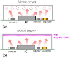
In a typical SMPS, noise can be generated not only by the aforementioned inductor and switches, but also the IC, capacitors, and other circuit components. With just a metal cover (can), the noise energy generated is free to be reflected off the metal and subsequently re-introduced back into the circuitry, and it can add to the original noise source. Adding a magnetic shield to the metal shield assists in completing a better EMI suppression solution. In this case, both µ’ and µ” need to be considered and will be dictated by magnetic shield thickness.
There are cases when the individual values of both µ’ and µ” for low-Q material are important. One example is in wireless magnetic-resonance applications where EMI suppression is required, and stable inductance is critical. If a high µ’ EMI suppression material is used to achieve better shielding performance, and is close the power coil, due to magnetic coupling, the permeability of the shielding material can increase the inductance value of the resonance coil. As a result, it may shift the resonance frequency and decrease performance. In this scenario, having a low µ’ value but a much higher µ” would be desired.
Another similar resonant power application is when a metal enclosure is used to prevent EMI emissions. If the magnetic field (flux) goes into the metal, this will cause a decrease of magnetic flux lines in the field and decrease the inductance, ultimately shifting the resonance frequency higher. In this case, the user should target a higher µ’ material to limit the impact on the desired magnetic field and not attenuate this field via a high µ” value.
Real-World Application
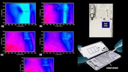
A Huawei P20 Pro handset was tested. This handset incorporates a metal shield that protects the address and data bus lines controlling the phone’s display (Fig. 4a). The yellow outlined area shows the size and location of the existing metal shield.
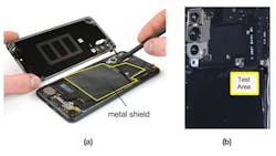
A test area was selected (Fig. 4b) and with the existing solution removed, a baseline was established using a near-field EMI tester. It was then compared to:
- The existing solution
- A hybrid ferrite + copper solution
- A permalloy material ungrounded solution
- A grounded permalloy material solution
The measured E-field (dBµV) level results are shown in Figures 5a through 5e.
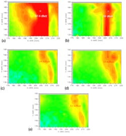
From this data, a few key points become evident. First, the magnetic material does impact the measurable E field value and, thus, attenuation level. Second, having a metal layer does help attenuate the EMI noise whether it’s with ferrite or permalloy magnetic material. Finally, being able to ground the shield further improves the shielding performance.
The permalloy shields used in Figures 5d and 5e, were substantially thinner, in the range of 20 µm, than all the other approaches which were in the 50- to 100-µm range. Additionally, this data is for a static frequency. When one views the attenuation over frequency, then it becomes even more obvious that many factors impact EMI noise suppression. Therefore, the choice of the magnetic material needs to be optimized for each unique application. This is shown for the two permalloy solutions in Figure 6.
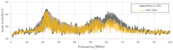
In this specific case, the noise suppression is greatly improved in the 55- to 80-MHz range. By simply grounding the magnetic shield, there’s roughly a 5-dBµV noise improvement in this range. At the peak noise frequency, around 22 MHz, there is a 2-dBµV improvement. More steps should be taken to improve on this if the compliance standard requires additional attenuation. Not shown is that the no-shield and existing-shield values of Figures 5a and 5b had their 67.6 dBµV and 59.0 dBµV respective noise peaks also occur at 22 MHz, which have been reduced down to 52.9 dBµV utilizing a permalloy material grounded shield.
Temperature Impact
Over temperature, the behavior of the magnetic material may change. For automotive, industrial, and other similar high-temperature applications, special consideration needs to be given to the magnetic shield’s properties. Three areas of importance are µ’, Bs, and the Curie temperature (Tc). µ’ tends to slowly increase with temperature. However, the magnetic-flux-density value tends to decrease with temperature, which will impact how much magnetic flux can be contained within the magnetic material. If the Bs value is substantially reduced, then EMI suppression performance will be altered.
Tc can be critical if magnetic shields are used in a high ambient environment. The total shield temperature would be the ambient plus self-temperature rise due to absorption during attenuation. If the Curie temperature is exceeded, the magnetic properties of the material can be permanently lost, and performance will be severely affected.
Each material’s temperature dependency is unique, and the user will need to obtain attenuation versus temperature information for any magnetic-sheet candidate based on the actual temperature environment. The user also needs to ensure the material’s operating temperature is high enough to ensure the actual temperature doesn’t approach the Curie temperature.
Other Considerations
Many times, designers prefer to put the EMI suppression solution right over or directly attached to some portion of the circuitry. This has been a “norm” for magnetic sheets as they’re typically made of non-conductive materials (e.g. ferrite) or have a non-conductive surface. With metal cans, there has always been a clearly understood “stay clear” area and height-clearance requirement.
Now with specialty hybrid or metallized magnetic sheets, the designer must give attention to ensuring that electrical shorts aren’t created by placing the EMI suppression sheet, with its conductive surface, and bridging across various components and causing failures. Many suppliers will use a non-conductive resin layer or offer alternative magnetic-shield layer stack-ups to ensure no conductive surface is exposed (Figs. 7a and 7b).
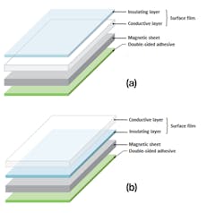
If the designer needs to make electrical contact to the shield, there is an option for such an approach, especially for grounding configurations. If the shield is to be placed directly on top of the components or placed on the bottom side of a metal can, it may not have enough clearance with an added EMI suppression shield discussed above. Thus, an insulted layer shield can be used to provide protection.
Conclusion
Every application’s EMI issues can be unique. What worked last time may not work for the next design. With so many different magnetic materials to choose from, it’s paramount to understand the frequencies and noise levels where EMI problems are prevalent, as well as understand how the materials’ parameters can impact noise suppression to comply with regulatory limits.
Key areas addressed were:
- Guidelines of choosing a lossy material rather than high Q material typically used for NFC/RFID applications
- Both a material’s µ’ and µ” values can be the key element in determining the right material.
- The impacts of shielding material, thickness, and the addition of metallization layers
- In the real-world example provided, it was shown that using a ferrite + metal layer hybrid material improves attenuation and even more improvement can be realized by grounding the shield.
- In general, having a metallized layer will provide some level of improved attenuation, and becomes more beneficial as the frequencies approach the GHz range.
Permanent magnets, with their dc magnetic flux, can pre-saturate thin magnetic shields. Therefore, if the end product contains them, they can reduce performance if not kept some distance away. Permittivity, an important magnetic material parameter, wasn’t addressed due to this being more critical for antenna performance rather than EMI suppression, but still impacts EMI shielding performance. The author hopes that, as a minimum, the reader now has a better understanding of magnetic material behavior and a better starting point in combatting their EMI woes.
Read more articles like this at the TechXchange: Delving into EMI, EMC and Noise
Chris T. Burket is Senior Marketing Engineer for TDK Corporation of America.
About the Author
Chris Burket
Senior Marketing Engineer, TDK Corporation of America
Comment About the Article
To join the conversation, and become an exclusive member of Electronic Design, create an account today!

Leaders relevant to this article: