Stuck in the Middle: How to Choose Your Next Bandpass Filter
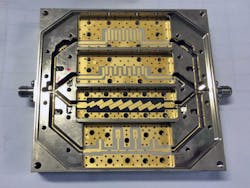
Bandpass filters are used in both wired and wireless communications systems, sensor applications, instrumentation, medical applications, and many others. When it comes to these types of applications, the goal is to pass signals of interest from point A to point B, while reducing noise and unwanted radiation from the signal source, other equipment, and the environment. Often different bandpass filters can be combined in a switched filter bank (see figure) that integrate the filters and switches, thereby providing better insertion loss, flatness, VSWR, and overall better performance of the device.
Such filters are used to transmit as well as receive in applications. For example, in a wireless transmit application, the filter is placed between the power amplifier and the antenna, ensuring that amplifier harmonics and out-of-band artifacts are significantly attenuated so that the transmitter does not cause interference with other wireless channels.
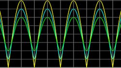
Bandpass filters ideally allow signals between a lower frequency and an upper frequency to pass with very little loss, rejecting signals outside the two frequencies’ range. The allowed range of frequencies is called the passband.
Bandpass-Filter Performance
Filters are often designed with published tables of numbers that are converted into inductors and capacitors to achieve responses, including Chebyshev, Butterworth, Gaussian, and others. Filters can also be synthesized, a process that begins with an equation and results in a network of physical elements.
The object of these exercises is always to determine inductance and capacitance values that achieve the passband and rejection criteria desired. Once the inductance and capacitance elements have been calculated, the theoretical performance of the filter is determined.
Bandpass-Filter Construction
Translating equations and specs to reality is, of course, often a challenge. A bandpass filter must be built so that it can:
- Handle the required power
- Fit within the allotted space
- Meet any other special criteria for its ultimate end use
- Remain on budget
Many different technologies are available for building the filter, and any given set of specifications can dictate a variety of ways of construction. Different filter elements and physical structures all have advantages and disadvantages that can be compared against the specific design criteria for your application.
Choosing the Best Bandpass Filter For Your Application
As with everything in this world, there are advantages, disadvantages, and tradeoffs that need to be considered and accounted for with each approach. So, how do you choose the proper technology for the job? Here’s a great example.
Suppose you need a 50-MHz bandwidth bandpass filter centered around 1 GHz and rejection of 50 dB at 200-MHz bandwidth (50-dB rejection at 900 MHz and below and at 1100 MHz and above). After consultation with readily available filter attenuation tables, you decide that a 5-pole filter design will do the job. This filter could be constructed with a variety of distributed or combination approaches, including:
- LC
- Cavity
- Comb
- Stripline, microstrip or suspended stripline
- Ceramic coaxial
- Helical
All of these filters will achieve the desired passband-rejection response specified. They are all 5-pole filters, and any one of them will work. Ultimately, the choice of which filter type to choose will come down to system requirements and priorities. These priorities could include tradeoffs among insertion loss, power handling, size, weight, temperature stability, ease of construction, cost, and other project parameters. Let’s examine the differences between these options.
Understanding the Different Types of Bandpass Filters
Lumped-element or LC filters
Lumped-element, or LC, filters provide the desired frequency response using inductors and capacitors (Ls and Cs). LC filters are perhaps the most familiar filter type to most engineers. Many alternatives are available for creating LC filters. Broadly characterized as distributed element filters, they can be made and used in multiple different ways. Distributed filters use transmission lines, short circuits, open circuits, air gaps, and dielectric materials in place of lumped inductors or capacitors.
To further expand the possibilities for their use, inductors and capacitors can be utilized in combination with distributed elements to craft specific performance characteristics. Many filter tables and synthesis tools start out assuming lumped elements are to be employed. Inductors and capacitors are readily available and are an attractive choice for any application already using printed circuit boards.
- Insertion loss: Worst
- Filter size: Small
- Power handling: < 10 W
- Typical Q: 50-200
- Cost: Low
Cavity and comb filters
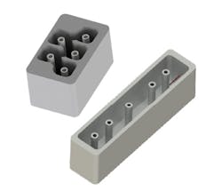
Cavity and comb filters both exploit distributed elements. They each use five rods that can be modeled as parallel resonant LC circuits. Each filter is carefully constructed so that the electromagnetic field from one rod couples energy to the next rod to achieve the desired filter bandwidth. For the comb filter, the wider the bandwidth, the closer the rods must be spaced. For the cavity filter, the wider the bandwidth, the larger the openings must be between the rods.
- Insertion loss: Best
- Filter size: Large
- Power handling: 100s of watts +
- Typical Q: 1000-5000
- Cost: High
Microstrip filter
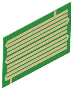
Another distributed approach is the microstrip filter. The one shown here is a hairpin design consisting of five u-shaped traces of precise spacing and length.
- Insertion loss: Worst
- Filter size: Medium-small
- Power handling: < 10 W
- Typical Q: 100-200
- Cost: Low to very low
Ceramic coaxial filter
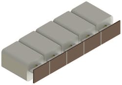
The ceramic coaxial filter may seem perplexing at first. There are five ceramic resonators, each functioning as a miniature coaxial cable shorted on one end and open on the other. Each shorted resonator acts as a parallel resonant LC circuit just like the cavity and comb filters. Energy is coupled from one to the other using a silver-plated ceramic plate printed with capacitors. The size of each printed capacitor determines the energy coupled from one resonator to the next. This sets the filter bandwidth. The ceramic coaxial approach shown here is a combination distributed lumped approach as it uses both transmission lines and capacitors.
- Insertion loss: 3rd place
- Filter size: Small
- Power handling: up to 50 watts
- Typical Q: 300-600
- Cost: Low to mid-range
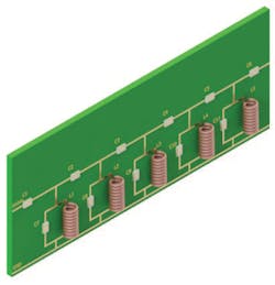
Helical filter
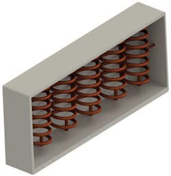
The helical filter is also a combination of lumped and distributed elements—it uses shorted inductors and electromagnetic coupling from inductor to inductor through air gaps.
- Insertion loss: 2nd place
- Filter size: Medium to large
- Power handling: up to 100 watts
- Typical Q: 600-1000
- Cost: High
Insertion Loss
If insertion loss is an important system parameter, you should consider the possibilities of each filter. Each of these filter types can be analyzed for loss by looking at the quality factor, or “Q” of the elements that make up each filter. The higher the quality factor of the filter elements, the better the insertion loss of the filter.
LC filters are made up of inductors and capacitors, so those are the two Q factors you should consider. Inductor Q is typically much lower than capacitor Q and tends to drive the losses in LC filters. When glancing at datasheets for inductors, you will notice that Q is typically below 200. Ranges of 50 to 100 are actually very common.
Using these numbers as a basis for comparison and knowing the Q values of the other filter technologies, you can infer the relative insertion loss performance.
Note that RC or RL resistor-capacitor- or resistor-inductor-based filters aren’t shown. They’re rarely used due to their increased insertion-loss characteristics.
Filter Size
Ultimately, if insertion loss is the overriding concern, cavity or comb would be the best filters for you. However, there’s a tradeoff between Q and size, which is the same as a tradeoff between insertion loss and size. Distributed filters get smaller as the frequency increases. So, it’s important to be aware of the relative sizes of the 1-GHz filter our example is considering.
Power Handling
Any of these filters will work just fine if the power levels going through the filter are relatively low (think just a few watts). If the power level will be on the higher side, you will definitely need to consider that when selecting your bandpass filter.
Among these filter candidates, the best for power transfer are the cavity and comb filters due to their grounded metal enclosures. It’s hard to beat a grounded metal enclosure for power handling and heat dissipation. In addition, both cavity and comb filters have the lowest insertion loss. Filter types with higher insertion loss will dissipate more of the signal passing through the filter as heat. Lower Q components have higher resistive losses. Lower insertion loss will improve the power-handling ability of the filter.
Cost
If economy is the driving factor in selection, microstrip and LC filters are the best choices. LC filters employ low-cost inductors and capacitors. Microstrip filters don’t use any components, but they may be priced slightly higher due to their controlled dielectric laminate. These laminates are generally more expensive than standard FR-4 PCBs. Next would be ceramic coaxial filters followed by helical, comb, and cavity filters, the most expensive options.
VSWR
All of these filters can achieve any desired voltage standing-wave ratio (VSWR), but because VSWR is affected by stray capacitance, inductance, and other physical nuances, the best VSWRs are achieved when individual filter characteristics can be adjusted. This is somewhat difficult with LC filters and near impossible with microstrip filters. In the case of LC filters, coils can be knifed, but variable capacitors are impractical most of the time. Similarly, ceramic coaxial resonators have a limited adjustment range.
The candidates for best VSWR performance are the larger filters—the cavity, comb, and helical. These all have built-in tuning adjustments and can achieve excellent VSWR performance by means of “tweaking” these adjustments.
James Price is VP of Engineering for Corry Micronics.
About the Author
James Price
VP of Engineering, Corry Micronics
James Price received a BS in Electrical Engineering from West Virginia University, Morgantown, W.V. in 1983. From 1985 to 1995, he was an engineer specializing in communications with RCA, which eventually became Lockheed-Martin in Camden, N.J. From 1995 through 2004, he designed CATV products for Tollgrade Communications, Cheswick, Pa. He’s currently VP of Engineering for Corry Micronics in Warrendale, Pa. His areas of focus include RF and microwave filters, multiplexers, switches, and antennas.
Comment About the Article
To join the conversation, and become an exclusive member of Electronic Design, create an account today!

Leaders relevant to this article: