Op Amps for Linear Designs: Back to the Basics
Download this article in PDF format.
Op amps are the basic building blocks for much of linear circuit design. You probably learned about them in college and even designed some products containing an op amp. As an electronic engineer, you will at some point in your career probably need to design a linear circuit.
If you’re not an advanced linear or analog circuit designer, perhaps the best way to fulfill your linear design needs is to use an op amp. These ICs are widely available, inexpensive, and can be configured in hundreds if not thousands of ways to satisfy most linear requirements. Here’s a summary and update on these versatile devices.
Sponsored Resources:
- What is an op amp?
- 3 common questions when designing with high-speed op amps
- The Signal e-book - 32 operational amplifier lessons
Background
The modern IC op amp is derived from older vacuum-tube designs used in analog computers. Analog computers were programmed by configuring op amps in multiple ways to implement different math functions (summer, integrator, etc.). Then you wired them up to simulate the system you are designing.
Then, transistor op amps came along. The IC op amps came into being in the late 1960s and early 1970s. The popularity of the op amp grew significantly. Today, hundreds of types and variations are available for almost any linear design.
This article explains the basic operation of general-purpose, voltage-feedback operational amplifiers. In addition, it points out some special things to look for in high-speed op amps.
Op Amps 101
An op amp is a direct-current differential amplifier that features very high gain, high input impedance, and a very low output impedance. By adding selected feedback and input components, you can make the op amp perform an incredible number of basic circuit functions.
Figure 1 shows the familiar op amp schematic symbol. The + and – signs identify the non-inverting and inverting inputs, respectively. The output VO is a function of the inputs and open-loop gain (AOL). The AOL is at least 100K and values over 1M are common. The gain is typically expressed in dB, like 120 dB that translates to 1 M.
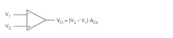
The output can be determined with the expression:
VO = (V2 – V1) AOL
Op amps are usually powered in two ways: with a traditional dual ± voltage supply or a single supply (Fig. 2). The dual supply lets the output swing both positive and negative. The single supply biases one input to set the output halfway between the positive supply and ground. Capacitive coupling on the input and output take care of any unwanted dc component.
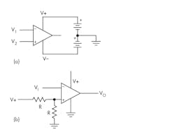
The supply voltages, of course, define the limits of the output-voltage swing. With bipolar designs, the output is generally a volt or so less than the supply voltages. In CMOS designs, the output can come within millivolts of the supply voltages.
Using the op amp in Figure 1 in an open loop isn’t common. Even with small input voltages, the amplifier typically saturates at one of the two output-voltage limits. For example, a bipolar op amp has dual 12-V supplies. The maximum output-voltage swing is ±10.5 V. Now assume V1 is −1.5 V and V2 is −1.2 V. Assume an AOL of 200K. The output is:
VO = [(−1.2) – (−1.5)] 200,000 = (.3)200,000 = 60,000 V
This is impossible, of course, so the output simply goes to the most positive level possible or +10.5 V.
Basic Circuits
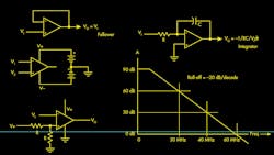
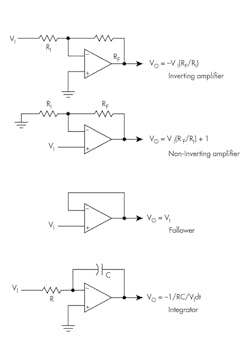
Figure 3 shows the most commonly used op-amp circuits. The feedback essentially makes the circuit mostly independent of the op-amp open-loop gain and other factors. The external components essentially define the circuit operation. You’re probably already familiar with these circuits, having used some variation in your own work.
Keep in mind that other op-amp specifications may need to be dealt with in your design. These include input offset voltage and current, common-mode rejection, unity gain frequency cutoff, noise, and slew rate. Some of these specifications can often be ignored because they’re so low and minimally invasive.
Three Common Issues When Designing with High-Speed Op Amps
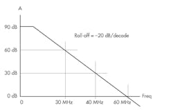
Op amps have a fixed gain-bandwidth (GBW) specification, which defines the frequency response of the device. Figure 4 shows one example. Note, the circuit amplifies dc; the ac roll-off is typically 20 dB/decade. Maximum possible frequency response is achieved at unity (0 dB) gain. Assume a GBW of 1000 MHz. If you set the gain at 100, the cutoff frequency is 10 MHz.
High-speed op amps are commonly defined as an op amp with a gain bandwidth of 50 MHz or more. Just what are the rules or protocols of working with a high-speed amp?
1. Some high-speed op amps have a minimum gain specification. Why?
Such op amps that are said to be decompensated have a second pole in the response curve above 0 dB. As a result, a minimum gain is necessary to ensure amplifier stability.
2. What are current amplifiers?
These amplifiers use current feedback instead of voltage feedback as in most common op-amp configurations. The primary benefit of using a current op amp is that the bandwidth doesn’t depend on the gain.
3. Why do high-speed op amps oscillate when I breadboard with them?
It’s caused by too much stray capacitance and inductance that results in unwanted feedback. This problem can usually be remedied with one or more of the following steps:
- Keep all component leads and connecting wires as short as possible. Reduce the length of all interconnecting wires and component leads.
- On PCBs, cut trace lengths.
- Reduce parasitics by improved signal-path routing; minimize the use of vias.
- Use ground planes but remove the copper below inputs and outputs.
- Use plenty of bypass capacitors and keep them close to the ICs.
The Signal eBook
There’s lots to know about op amps. To learn more, you have access to an online eBook and op-amp reference that contains 32 operational-amplifier lessons. This free eBook is collection of short, practical, and intuitive lessons with the answers to some of the most common op-amp questions.
Written by Bruce Trump, an experienced engineer for TI, the eBook is loaded with useful insights, solutions, and recommendations. Download it now and keep it for reference. You will be a better linear designer as a result.
Sponsored Resources:
About the Author

Lou Frenzel
Technical Contributing Editor
Lou Frenzel is a Contributing Technology Editor for Electronic Design Magazine where he writes articles and the blog Communique and other online material on the wireless, networking, and communications sectors. Lou interviews executives and engineers, attends conferences, and researches multiple areas. Lou has been writing in some capacity for ED since 2000.
Lou has 25+ years experience in the electronics industry as an engineer and manager. He has held VP level positions with Heathkit, McGraw Hill, and has 9 years of college teaching experience. Lou holds a bachelor’s degree from the University of Houston and a master’s degree from the University of Maryland. He is author of 28 books on computer and electronic subjects and lives in Bulverde, TX with his wife Joan. His website is www.loufrenzel.com.
Comment About the Article
To join the conversation, and become an exclusive member of Electronic Design, create an account today!

Leaders relevant to this article: