IO-Link Ref Design Pairs Configurable Analog Input/Output with Transceiver Boards
An experienced circuit-design EE once clarified his view of the hierarchy of IC-vendor design support: High-performance, feature-rich ICs were good, application circuits were better, but complete reference designs, well…they were the best. That’s understandable, given the complexity of many ICs and how much has to be “just right” in circuit and software to get a number of these ICs to function before even being able to explore and exploit their full potential (and even meeting regulatory mandates).
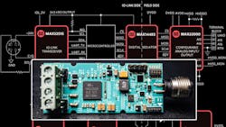
Addressing this need, Maxim Integrated announced the MAXREFDES177# IO-Link reference design (Fig. 1). It leverages the flexibility of the MAX22515 IO-Link transceiver IC and enables setting the many modes of the MAX22000 software-configurable analog I/O IC. The two-IC chipset solution takes advantage of IO-Link’s two-way universal interface, which allows every IO-Link sensor, actuator, or I/O expansion module to be interchangeable due to a standard hardware interface. It also provides software-defined performance parameters and selectable analog-input/output performance modes.
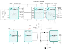
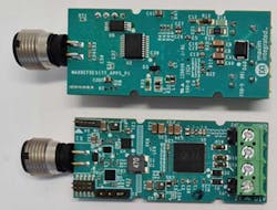
The MAXREFDES177# design includes a MAX22000 industrial universal analog I/O device that’s fully software-configurable for all common industrial analog input/output, voltage, and current ranges. A MAX14483 six-channel, 3.75-kVRMS digital-galvanic isolator, a MAX22515 IO-Link device transceiver; and an Atmel ATSAM low-power microcontroller are all tied together via a third-party device software stack. The complete reference design fits on a 61- × 25-mm printed circuit board (PCB) (Fig. 2).
The analog (field) side uses a four-way PCB terminal block and includes full (galvanic) isolation from the IO-Link side, while an isolated power supply is derived from the L+ (24 V) supply at the IO-Link master connection. The MAXREFES177# sets the linear range at 105% and full-scale range at 125% of the nominal range. The board contains a male M12 connector to connect to a compliant IO-Link master using a standard M12 cable.
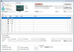
The analog side of this IO-Link uses the Technologie Management Gruppe Technologie und Engineering (TMG TE) IO-Link device stack to communicate with any IO-Link having a version 1.1-compliant master, and well as with user configuration screens (Fig. 3).
The MAXREFDES177# doesn’t require external protection devices such as varistors or transient-voltage-suppression (TVS) diodes due to the surge protection integrated in the MAX22515 at the IO-Link interface. This reference design meets both the IEC 61000-4-2 standard for electrostatic discharge (ESD) up to ±4 kV and the IEC 61000-4-4 standard for electrical fast transient (EFT) ±4 kV, and is designed to provide surge-withstand capability of 2 A at t = 1.2/50 μs up to ±1.0 kV. Additional TVS protection circuitry is included as part of the field-side analog I/O circuit.
The $65 reference design and each of its constituent parts has its own home page and datasheet, as expected: MAXREFDES177# IO-Link Universal Analog I/O Reference Design; the MAX22000 Industrial Configurable Analog I/O; and the MAX22515 IO-Link Transceiver with Integrated Protection.
References
Wikipedia, “IO-Link”
IO-Link Consortium, “IO-Link FAQ”
Maxim Integrated, “IO-Link Handbook”
Profinews, “Learn All About IO-Link – the Basics”
About the Author

Bill Schweber
Contributing Editor
Bill Schweber is an electronics engineer who has written three textbooks on electronic communications systems, as well as hundreds of technical articles, opinion columns, and product features. In past roles, he worked as a technical website manager for multiple topic-specific sites for EE Times, as well as both the Executive Editor and Analog Editor at EDN.
At Analog Devices Inc., Bill was in marketing communications (public relations). As a result, he has been on both sides of the technical PR function, presenting company products, stories, and messages to the media and also as the recipient of these.
Prior to the MarCom role at Analog, Bill was associate editor of their respected technical journal and worked in their product marketing and applications engineering groups. Before those roles, he was at Instron Corp., doing hands-on analog- and power-circuit design and systems integration for materials-testing machine controls.
Bill has an MSEE (Univ. of Mass) and BSEE (Columbia Univ.), is a Registered Professional Engineer, and holds an Advanced Class amateur radio license. He has also planned, written, and presented online courses on a variety of engineering topics, including MOSFET basics, ADC selection, and driving LEDs.
Comment About the Article
To join the conversation, and become an exclusive member of Electronic Design, create an account today!

Leaders relevant to this article: