What’s the Difference Between an Integrated ADC and a Standalone ADC?
Members can download this article in PDF format.
What you’ll learn:
- The tradeoff between integrated and standalone ADCs regarding performance, specification, complexity, robustness, and cost.
- How to evaluate which analog technology to use to meet your application needs.
- Difference between ADC accuracy and ADC precision and how to determine if accuracy or precision matter in your application.
Today’s complex distributed systems are acquiring and analyzing more analog data while also offering monitoring and diagnostic capabilities. As these systems become increasingly complex, the critical need to accurately measure analog signals continues to grow.
To better meet these precision requirements, designers are often left to choose between a microcontroller (MCU) with an integrated analog-to-digital converter (ADC) or a standalone ADC. So, what’s the difference between an integrated ADC and a standalone ADC, and which is better for your application?
First, let’s explore the performance tradeoffs of integrated and standalone ADCs, then we can determine how to make the right choice for your application.
Integrated ADCs: Performance Tradeoffs
Process Technology
Let’s look at the ADC from the perspective of the semiconductor integrated-circuit (IC) engineer doing the integrated ADC’s design. Since the ADC is a peripheral to the MCU, an integrated ADC designer will tend to use an MCU-friendly process like a small geometry 28-nm process, which offers a good digital density and high-speed transistors for the MCU. While the small geometry process may also reduce the size of the ADC, there are significant tradeoffs to this approach:
- The relative cost of the ADC will increase due to the substantially higher cost of the process.
- The size of components available on the process will increase the inherent noise of the ADC, specifically thermal noise, or kT/C noise.
- The larger capacitors used in ADC designs to reduce thermal noise will be a significant design constraint on a smaller geometry process (it’s geometrically more challenging to implement the components needed for analog performance on smaller geometries).
- Smaller geometry capacitors will introduce leakage and nonlinearities into the design.
- Matching issues that aren’t as controlled as they are in larger geometry processes, such as 90 nm or 180 nm, will lead to a lack of control in the manufacturing process as well as variations in the parametric performance of the ADC.
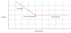
Another challenge with the small geometry process is 1/f noise. 1/f noise dominates at low frequency and decreases from dc by roughly a factor of 1/√ (frequency). At higher frequency, white noise starts to dominate the 1/f noise at a point called the corner frequency (Fig. 1). If a designer wants to improve performance by using digital compensation techniques such as averaging or oversampling, they need to ensure that they’re only sampling values that contain white noise and not 1/f noise.
The problem for smaller geometry processes versus larger geometry processes is that the corner frequency shifts higher—significantly higher. This is precisely why digital filtering techniques, such as averaging or oversampling, don’t improve system performance in systems with high 1/f corner frequencies. In fact, in some cases, digital filtering techniques can decrease system performance. In short, the limitations of the process will ultimately dictate the achievable performance of the ADC (Fig. 1, again).
IC Layout
If the MCU is collocated on the IC next to the ADC, the ADC’s analog performance will be affected in the following ways:
- The fast-switching MCU will introduce switching noise and ground bounce into the circuit, especially since the size is reduced to the area of an IC, making issues exponentially more difficult to address.
- Clock synchronization and management techniques can be used to minimize these effects, but the interaction of peripherals and asynchronous events will still impact ADC performance.
Temperature
The third challenge is one of the worst enemies of analog performance: temperature. The MCU sitting next to the ADC will act like a variable temperature source, going from high-speed active power (hot) to standby, sleep, or hibernate (not so hot). Such a temperature change causes bad things to happen to electronic circuits (especially analog circuits).
To achieve predictable performance in a time-varying temperature environment, temperature-compensation circuitry needs to be added. This increases the size and cost of the system, a luxury that integrated ADCs find difficult to afford.
Test Cost
MCUs are digital devices and, as such, they’re tested on digital test platforms using digital test vectors. The digital test solution is optimized for testing of digital parameters in the shortest test time to get the most volume of units through in the least amount of time.
If these digital test platforms have analog test capability, it’s often limited, low-performance analog test capability. This makes testing levels of analog performance difficult due to the lack of accuracy and noise in the test platform. That’s why the specifications of analog peripherals on MCUs are typically either “guaranteed by design” or “guaranteed through characterization.” Some other constraints on these testers are:
- They’re often only capable of testing the analog function, or what the analog is doing, and often don’t have the ability of accurately testing analog performance over temperature.
- The limitations of the tester subsequently limit the performance specification of the ADC (you can’t test a device specified as a 1-Msample/s, 12-bit ADC performance if your tester only has 100-ksample/s, 8-bit capability).
- It’s not practical to add precision analog test capability to a digital test platform. It would require an order of magnitude increase in test cost, which would have a corresponding increase in the device cost.
Standalone ADCs: Performance Tradeoffs
Process Technology
For the standalone ADC, since the ADC is the main component and the MCU is a peripheral to the ADC, an IC designer may instead choose to use an ADC-friendly process, like a 180-nm process, which offers larger well-matched components for the ADC. However, this process has one fundamental tradeoff that will limit the performance of the ADC.
By using a larger geometry process, the designer will not have an optimized process for digital processing or serial communications. Instead, it will have to rely on analog design and layout techniques to ensure digital performance. This lack of small digital density and speed optimization will increase the cost of the device and the digital performance will be constrained by the limitations of the process.
IC Layout
When it comes to managing noise, a standalone ADC has two advantages over the integrated ADC approach:
- No other peripherals active on the device will impact analog performance.
- Switching noise can be managed since critical analog functions could be performed while the clock is quiet.
Temperature
Again, the worst enemy of analog performance is temperature, but standalone ADCs offer advantages over integrated ADCs in this case because:
- There’s no time-varying temperature source (like the MCU) next to the ADC.
- Since this process is analog-friendly, analog-friendly temperature-compensation circuitry can easily be added to minimize the impact of temperature variations.
Test Cost
ADCs are analog devices, and as such, they’re tested on analog test platforms using precision analog equipment. However, this comes with factors that greatly increase the test cost.
Unlike digital test platforms, which have tightly controlled variation between testers, analog test platforms tend to have a lot of variation between load boards, analog signal generators, and analog measurement systems. This usually increases the test cost due to the need for calibration. Also, to guarantee analog performance over temperature, compensation techniques for analog circuits often require a temperature trim be applied at final test to guarantee low temperature drift.
Now that we know mixed-signal and analog tradeoffs, how do they affect accuracy and precision?
Accuracy and Precision
Accuracy and precision are two terms often used interchangeably, but they have very different meanings. Accuracy is the ability of the measurement to match the actual value and is needed when trying to measure a specific value. Precision is the ability of a measurement to be consistently reproduced or, in other words, the repeatability of a measurement. The more precision in a measurement, the more you can discern smaller differences.
For example, consider a weigh scale. If 1.000 troy ounces of gold are placed on a weigh scale, and it’s measured three times, indicating 1.001, 1.000 and 1.000, then that is high precision (0.0005-ounce standard deviation) and high accuracy (0.03% error after averaging). If a different scale gets readings of 1.018, 1.017 and 1.018 ounces, then this is still considered to have high precision (0.0005-ounce standard deviation), but the accuracy is lower (1.8% error).
So, which is more important, accuracy or precision? Well, it depends on the application, but there are many cases where both accuracy and precision are needed.
Accuracy
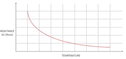
To determine if you need accuracy, it’s important to first understand how the sensor is being used in your application. Let’s consider a temperature measurement example using a negative-temperature-coefficient (NTC) thermistor. The first thing that stands out in the resistance versus temperature plot of the NTC is the nonlinearity of the device (Fig. 2).
If a designer only needs to measure the NTC at lower ambient temperatures, then a lower-resolution ADC can be used. If there’s a need to measure temperature across the entire temperature range, then the worst-case conditions must be considered at higher ambient temperatures, which means using a much-higher-resolution ADC.
To equate that to system accuracy, define the temperature range and calculate how much temperature accuracy is needed over that range. The temperature range would be converted to an analog voltage-input range for the ADC. The accuracy would be the smallest deviation from the measured analog input that the application could tolerate.
Precision
Next, consider precision. Ideally, precision needs to be better than accuracy. If a temperature reading in the feedback loop of a system is being used, then the feedback loop should be very stable. If the precision is worse than the accuracy, then the feedback loop could go unstable.
ADC Measures of Accuracy and Precision
The important ADC specifications impacting accuracy are integral nonlinearity, differential nonlinearity, offset, offset drift, gain, and gain drift. To determine accuracy, the contributions of these error sources need to be assessed. Similarly, precision is defined by the term effective number of bits (ENOB). It tells you the deviation you will see in a set of ADC readings from the true mean. In other words, 68.3% (or one standard deviation from the mean) of ADC readings you take will fall in the range defined by ENOB.
To illustrate, let’s go back to the NTC example. Pretend that the output of the NTC calibrated to be linear over the entire temperature range to give 0 V at −40°C and 2.5 V at 85°C, and that we want to measure with 1°C accuracy. Therefore, 1°C accuracy over a 125°C range is 0.8% accuracy over the range.
Assuming we have a 12-bit ADC with 1 LSB total error and a 2.5-V input range, the accuracy of the measurement from the ADC can be expected to be 1/4096 or 0.024% or 2.5 V/4096 bits or 610 µV/bit, which is 33 times the accuracy that’s needed. Therefore, theoretically, a 12-bit ADC should have enough accuracy to meet these requirements.
Now let’s have a closer look at an example 12-bit, 400-ksample/s integrated ADC inside a newly released MCU.
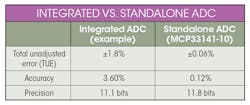
In its datasheet, the total unadjusted error (TUE) is specified as ±1.8% from −40 to 85°C. A 6-bit ADC with 1 LSB total error gives an accuracy of 1.6%, so what happened to the other 6 bits on the 12-bit ADC? Not only that, but the error can also be positive or negative—there can be a 3.6% or 90-mV variation in readings from the ADC. In such a case, the large gain error over temperature contribute heavily to the reduced accuracy. This large error in accuracy is a by-product of the limitations inherent in the process technology.
In fact, be very careful when reading datasheets for integrated ADCs. In some cases, the datasheet for the integrated ADC only specifies the ADC performance using an external voltage reference due to the noise, drift, and poor performance of the integrated voltage reference, which defeats the purpose of using integrated analog components. Therefore, the accuracy of the integrated ADC isn’t good enough in this case to meet our 0.8% requirement.
So, what about the precision of the integrated ADC? Looking at the precision specification, the ENOB is 11.1 bits, which translates to about 1.1-mV resolution on the 2.5-V analog input signal. The precision is about 80 times better than its accuracy. The result is that the integrated ADC has an error of 90.7 mV and a precision of about 1.1 mV rms. The accuracy of the integrated ADC can be improved by using an external reference. But, because of how the ADC is specified, it’s unknown how much the external reference will improve accuracy performance.
Next, consider a standalone ADC, like Microchip Technology's MCP33141-10.
Looking at the accuracy of this 12-bit, 1-Msample/s ADC, calculate the TUE and make a comparison to the integrated ADC. The TUE over the -40°C to 125°C temperature range equates to ±0.06%. That is 30 times better accuracy than the integrated ADC and it is over a wider temperature range. In terms of precision, the standalone ADC has an ENOB of 11.8 bits, so in this example the precision of the standalone ADC is about four times better than its accuracy. The result is that the standalone ADC has an error of 2.9 mV and a precision of about 0.7 mV rms.
In this comparison, the precision of an integrated and standalone ADC is very close (see table). However, even though the integrated ADC was precise, it could not achieve the 1% accuracy requirement. Only the standalone ADC can meet the 1°C or 0.8% accuracy requirement over temperature for an NTC temperature sensor.
System Considerations of Accuracy and Precision
The problem with only looking at the precision of the ADC is that it doesn’t consider the variables in the system (or systems) using the ADC. If the ADC is accurate and precise, then the output of the ADC will be consistent across all devices and all conditions, versus only being consistent for a given device or a given condition.
Therefore, if accuracy or consistency aren’t needed from system to system or across all conditions that a system needs to work, the advantages of using an integrated ADC are lower complexity, size, and price. Complexity will be lower with an integrated ADC since there’s no need to develop software to interface to an external ADC, nor will there be a need to account for the placement and routing of analog and digital signals to and from the ADC. Integrating the ADC with the MCU means the overall board footprint will also be smaller. Furthermore, the price of an MCU with an integrated ADC is typically lower than the combined price of an MCU and a standalone ADC.
However, if precision, accuracy, and consistency are needed from system to system or across all conditions that a system needs to work, be very careful in the choice of the ADC. Don’t be the designer who falls into the trap of believing that device variation will be small and digital compensation techniques can be used to compensate for inaccuracy or inconsistent analog performance. Remember that digital compensation techniques could potentially reduce the system’s accuracy while increasing the complexity due to the inherent limitations of the process.
Also, ensure that the ADC and voltage reference specify not only accuracy, but accuracy over temperature. If the ADC doesn’t specify accuracy over temperature, then the risk is high that process, manufacturing, test, and temperature variations will show up as errors in the system. Even worse, these variations aren’t deterministic. One device may have significant positive gain drift while another device may exhibit significant negative gain drift. These wide variations could lead to instability in the system.
When deciding between an integrated ADC and a standalone ADC, it’s simply a choice between cost, accuracy, and consistency of performance. Once you define the accuracy or consistency of the performance needed, then the selection becomes easy.
About the Author
Iman Chalabi
Product Marketing Engineer, Mixed Signal Linear Business Unit, Microchip Technology
Iman Chalabi is a product marketing engineer in Microchip Technology’s mixed signal linear business unit. In this role, he is helping to expand Microchip’s analog-to digital converter portfolio. Iman graduated from the University of Toronto with a degree in electrical engineering and marketing.


