How to Best Calculate the DAC Signal-Chain Error Budget

What you'll learn:
- What are the kinds of errors that plague signal chains?
- How to use the error budget calculator.
Electrical signal chains can be found in various forms. They may consist of different electrical components, including sensors, actuators, amplifiers, analog-to-digital converters (ADCs), digital-to-analog converters (DACs), or even microcontrollers. The accuracy of the overall signal chain plays a decisive role.
To increase the accuracy, it's first necessary to identify and minimize the respective errors in the individual links. Depending on the signal-chain complexity, this analysis can turn into a daunting task. This article presents a precision DAC signal-chain error budget calculation tool. It will describe the individual error contributions of the components connected with DACs. Finally, it will demonstrate step-by-step how this tool can be used to identify and correct these issues.
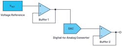
A precision DAC error budget calculator is precise, easy to use, and can help developers select the most suitable component for a particular application. Because DACs don't usually appear alone in the signal chain, but instead are connected to voltage references and operational amplifiers (as reference buffers, for example), these additional components and their respective errors must be considered and summed. To better understand this concept, we first look at the individual error contributions of the main components, as shown in Figure 1.
Types of Errors
The voltage reference has four main error contributions. The first is associated with the initial accuracy (initial error), which indicates the variation in output voltage as measured in production test at a defined temperature of 25°C. Added to that are the errors related to the temperature coefficient (temperature-coefficient error), load-regulation errors, and line-regulation errors. The initial accuracy and temperature-coefficient error contribute the most to the total error.
In op amps, the input offset voltage error and the tolerance error of the resistors have the greatest impact. The input offset voltage error refers to a low differential voltage that must be applied to the inputs to force the output to 0 V. The tolerance error of the resistors is the gain error caused by the corresponding tolerances used for setting the closed-loop gain. Other errors are caused by the bias current, the power-supply rejection ratio (PSRR), the open-loop gain, the input offset current, the CMRR offset, and the input offset voltage drift.
For the DAC itself, various types of errors are given in the datasheet—for example, the integral-nonlinearity (INL) error, which relates to the difference between the ideal output voltage and the output voltage measured for a given input code. Further types are the gain, offset, and gain temperature-coefficient errors. Sometimes, these are all grouped together to form the total unexpected error (TUE). This relates to the measurement of the output error in consideration of all DAC errors—that is, the INL, offset, and gain errors, as well as the output drift over the supply voltage and temperature.
Since the different sources of error usually aren't correlated, the most precise approach for calculating the total error in the signal chain is the root-sum-square method:
Total Error = √(Error VREF)2 + (Error Buffer 1)2 + (Error DAC)2 + (Error Buffer 2)2
Collecting the errors of the respective components is typically a tedious task, so we can simplify this with the error budget calculator to derive an equally precise calculation.
Using the Precision DAC Error Budget Calculator, Step-By-Step
First, using the error budget calculator, select from three DAC types: voltage-output DAC, multiplying DAC, and 4- to 20-mA current-source DAC. Next, set the desired temperature range and the supply voltage ripple for the error calculation. The latter is decisive for the PSRR error. Once these values are entered, the calculator generates a chart showing the respective error contributions of the individual components in the signal chain (Fig. 2).
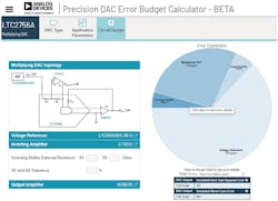
The total error in this example is mainly influenced by the voltage reference. An improvement in this signal chain could be achieved through the use of a more precise reference module.
The DAC's integrated resistors, which are responsible for the comparison of the internal inverting amplifier and thus for an improvement in the accuracy, make a decisive contribution to the total error of the DAC. In DACs without integrated resistors or an internal inverting amplifier, these parameters can be specified separately (Fig. 2, again).
About the Author
Thomas Brand
Field Applications Engineer, Analog Devices
Thomas Brand began his career at Analog Devices in Munich in October 2015 as part of his master’s thesis. From May 2016 to January 2017, he was part of a trainee program for field applications engineer at Analog Devices. In February 2017, he moved into the role as field applications engineer. Within this role, he is mainly responsible for large industrial customers. Furthermore, he specializes in the subject area of industrial Ethernet and supports appropriate matters in central Europe.
He studied electrical engineering at the University of Cooperative Education in Mosbach before completing his postgraduate studies in international sales with a master’s degree at the University of Applied Sciences in Constance.
Comment About the Article
To join the conversation, and become an exclusive member of Electronic Design, create an account today!

Leaders relevant to this article: