Filtering and Suppressing EMI in the Smart Factories of the Future
This article is part of the TechXchange: Delving into EMI, EMC and Noise
The latest industrial revolution, Industry 4.0, is bringing increasing numbers of smart and connected machines to the factory floor. These systems need to coexist without being disrupted by unintended electromagnetic interference. Given the growing complexity of industrial systems and the tasks they perform, the consequences of failures can result in expensive maintenance costs and lost production.
Established regulations on electromagnetic compatibility include the U.S. Federal Communications Commission's (FCC) Part 15 Rules and Regulations and the E.U. EMC Directive 2014/30/EU. The FCC splits up equipment for industrial and residential environments into Class A and Class B, respectively. While there are exemptions for some types of digital industrial equipment, the FCC “strongly recommends” that manufacturers make sure products meet these technical specifications.
The European Machinery Directive 2006/42/EC requires machines marketed in the E.U. to be marked "CE." That signals compliance with EMC regulations that apply to the product in question. To ensure compliance, vendors need to refer to specifications referenced in the standards. These include IEC 61000-6-2 and 61000-6-4, which define electromagnetic immunity and emission requirements for electrical and electronic equipment used in industrial settings.
The International Special Committee on Radio Interference (CISPR) has also established a separate standard, CISPR 11, which lays out emissions limits and methods of measurement for industrial, scientific, and medical (ISM) equipment. The European norm EN 55011 is based on CISPR 11 and is referenced in the European EMC Directive.
Safety-related systems are typically subject to even tougher specifications. EN 62061 is a machinery-specific requirement under the general functional safety standard, IEC 61508. IEC technical specifications IEC/TS 61000-1-2 and IEC 61326-3-1 cover EMC requirements concerning functional safety within this group.
Conducted and Radiated Interference
Interference exists in various frequency ranges, including noise at harmonics of the AC line frequency, which can reach up to 2.5kHz, as well as low-frequency noise and higher frequency conducted and radiated noise. While low-frequency noise is not regulated, limits are placed on both emissions and the system's susceptibility to harmonic noise from 50/60Hz to 2.5/3kHz, conducted RF noise from 9kHz to 30MHz, and radiated noise from 30MHz to 3GHz.
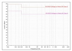
There are international standards that specify maximum noise in these frequency ranges. Figure 1 illustrates the limits for conducted noise from 150kHz to 30MHz as specified in EN 55011/CISPR 11.
Switched-mode power supplies, switching dc-dc converters, motors, drivers, and other electronic modules used in industrial tools and factory machines tend to be large sources of electromagnetic noise. These modules are sometimes designed and built in-house by equipment manufacturers (OEMs). But OEMs also often source them from external suppliers. Typically, machine builders or system integrators need to take responsibility for EMC compliance at the system level.
The rules applying to variable-frequency drives (VFD) are one example of this. Industrial VFDs are covered within the EMC product standard known as IEC 61800-3. Responsibility for ensuring EMC compliance depends on whether the device is marketed as a complete drive module (CDM) or basic drive module (BDM). A BDM generally needs more engineering effort to integrate with the finished product. In this case, the OEM or system integrator using the BDM is expected to handle the EMC testing and other product approvals.
Conversely, a CDM tends to be supplied to end customers that have minimal expertise with EMC themselves. That means CDM vendors need to take responsibility for EMC compliance.
Filters
The usual way to prevent interference from entering or escaping from equipment is through the use of filters. Filters are designed to attenuate signals at unwanted frequencies when placed at appropriate spots, such as power input and output lines. These include passive components favored for their ability to attenuate noise signals greater than the maximum permitted amplitude at any given frequency across the regulated range.
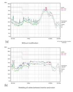
Some three-phase motor and drive units can generate excessive noise in certain frequency ranges, as shown in Figure 2a. A high-pass filter can be added to the design to attenuate frequencies starting at 4MHz, keeping noise emissions within the stipulated maximum across the full frequency range as in Figure 2b.
Switched-mode power supplies usually add significant noise at frequencies close to the switching frequency, which is typically in the range 100kHz to 400kHz. Noise is present at the fundamental and harmonics of the switching frequency. These can cover a broad spectrum from 10kHz to 50MHz. Switching causes both current and voltage transients. Voltage transients (high dV/dt) tend to couple through capacitances, while current transients (high di/dt) couple through magnetic components. Other sources of power supply noise include differential-mode noise due to the bridge rectifier.
A powerline filter is commonly used to stop noise from entering or leaking out of equipment through the main power cable. These types of filters combine X and Y capacitors to attenuate differential and common-mode noise, which is also addressed by common-mode inductors (Figure 3). The common-mode inductor comes with two coils wrapped around a single core that lets common-mode currents flowing in opposite directions to create equal and opposite flux, canceling out the common-mode noise in the process.
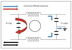
X and Y capacitors are special types of boxed capacitors designed specifically for use in mains-powered equipment. As a rule, X capacitors are placed in across-the-line (phase to phase or phase to neutral) locations, and Y capacitors are connected from "phase-to-ground," as shown. Therefore, a short circuit across the two capacitors, especially the Y capacitor, could lead to catastrophic failures and should be avoided at all costs. These capacitors attenuate noise entering the equipment and also prevent electromagnetic noise generated by the power supply being conducted back into the AC line.
X and Y capacitors need to be able to withstand applied voltages significantly above the nominal supply voltage, along with high voltage, short duration transients as a result of events like lightning strikes. This ability to withstand high voltage transients gives EMI capacitors the name "safety" capacitors. They must also be able to ensure stable safety and filtering mechanisms in high temperatures, humidity, and other harsh conditions over the full operating voltage range.
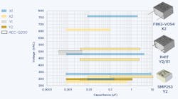
The properties of polypropylene film capacitors, such as KEMET’s F862-V054 and R52P metalized polypropylene film X2 capacitors and R41T Y capacitors, make them a strong choice for use as X and Y filter capacitors. They are also relatively low cost, and their self-healing properties reduce the risk of short circuits. These parts also help to make sure the device maintains its capacitance over an extended period of time.
Capacitor Selection
All three devices meet AEC-Q200 requirements for auto electronics as well as IEC603814-14 (Grade IIB and IIIB), confirming their ability to operate in harsh environmental conditions. Some filter capacitors, such as the R41T series, can be used in Y2 and X1 "line-to-ground" and "across-the-line" connections. The R41T series is also suited to be used in situations where the failure of the capacitor could lead to electric shocks or other dangers (Fig. 4).
It is also essential to consider the degradation of the component over the years to make sure enough capacitance remains at the end of the intended lifetime of the equipment. The effects of temperature, humidity, and bias (THB) when in operation can cause a loss of capacitance over the lifetime of the device. The loss is difficult to calculate using datasheet information alone. But there are a number of life-expectancy tools that engineers can use to make this assessment. However, it's critical to use a tool that takes into consideration a variety of conditions (Fig. 5).

Suppressing Conducted Emissions using Chokes
Selecting the right choke based on the magnetic core material is crucial to fine-tuning the frequency-based impedance (or insertion loss) of the choke. This specifically reduces the conducted noise at unwanted frequencies or frequencies where the noise surpasses the set limits for conducted and radiated emissions. Such chokes are also useful for making the system more immune (also called "conducted immunity") to external conducted disturbances (mainly current transients in this case). These disturbances can interfere and possibly also damage internal electronics.
The current passing through the choke also impacts the thickness of the choke coil as well as the thickness of the core due to saturation effects. Each core material has a different characteristic impedance depending on frequency and saturation characteristics as well as current. A wide range of magnetic materials is important, as it allows a design engineer to pick out a solution that specifically meets their needs.
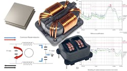
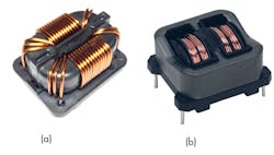
For some applications, one dual-mode choke could effectively replace two different chokes. Dual-mode chokes are common-mode choke coils with an additional magnetic path (or magnetic nose) to generate enough parasitic inductance to offer differential mode impedance inside a common mode choke (Fig. 6).
Additionally, there is also the option to explore components with special housing or winding techniques, such as those available from KEMET, to further optimize the thermal behavior and frequency coverage by reducing parasitic capacitances. That also boosts the resonance frequency point.
Suppressing Radiated Emissions
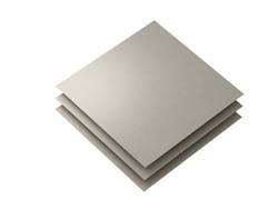
Electromagnetic shielding may also be needed to suppress radiated interference at higher regulated frequencies entering or leaving the equipment. In many cases, the shield is a magnetic component designed into the equipment at an early stage. On the other hand, problems with radiated interference can arise at a late stage of development, when a redesign may not be practicable or economic. In this case, flexible EMI-absorbing materials such as KEMET’s Flex Suppressor family can be helpful.
These materials comprise a composite of soft magnetic alloy and polymeric binder with an adhesive backing and optional protective coating. These sheets are particularly effective when removing noise in the UHF and SHF radio frequency range. For VHF and UHF frequency ranges, EMI cores made from different magnetic materials, combined with a different number of wire-turns, can yield the desired insertion losses in radiated emissions spectra (Fig. 7).
Conclusion
In the industrial space, equipment makers, system integrators, and parts suppliers need to understand their responsibilities when it comes to EMC testing and conformity in their products. The regulations detailing the EMC/EMI standards and test requirements are already well-established.
Conducted noise up to 30 MHz can be attenuated by inserting filters in places such as on power lines, while polypropylene film X and Y capacitors and magnetic chokes are also frequently used in these systems. Solutions to deal with sources of radiated noise at frequencies above 30 MHz are also in high demand. Special suppression materials are available that effectively absorb energy at unwanted frequencies and can be applied at any stage of development.
Read more articles like this at the TechXchange: Delving into EMI, EMC and Noise
About the Author
Pranjal Srivastava
Field Applications Engineer, KEMET
Pranjal Srivastava is a field applications engineer at KEMET. He has a master’s degree in Microsystems Engineering from Albert-Ludwigs-Universität Freiburg in Germany and a bachelor’s degree in Electronics and Communication Engineering from JIIT, Noida, India. Prior to KEMET, Pranjal worked four years as an automotive hardware engineer and was involved in the design and validation of EMC-compliant hardware for battery management systems. He also worked on steering-angle sensors for global auto OEMs.
Comment About the Article
To join the conversation, and become an exclusive member of Electronic Design, create an account today!

Leaders relevant to this article: