Automatic Impedance Matching in RF Design

This article is part of the Analog Series: Back to Basics: Impedance Matching
What you’ll learn:
- What is impedance matching?
- Applications of impedance matching.
- Impedance matching and design considerations.
Impedance (Z) matching is an essential part of most RF circuit design. Regardless of what you’re designing, getting as much power to a load is a top target. Impedances must be matched to transfer the maximum amount of signal power between stages. And in power amplifiers (PAs), impedance matching is critical to getting the maximum power to the final load and maintaining PA linearity. Impedance matching to an antenna in a receiver or transmitter is an essential process.
Some loads are constant; thus, a single fixed Z-matching circuit can be used. But in other applications, that final load may change, or the frequency of operation will change, meaning that a fixed Z-match circuit will not produce the desired results. For these applications, a variable matching network that you can adjust is needed. Better still is a variable and automatic Z-match circuit that adjusts itself to the immediate load or frequency conditions.
Auto Z matching is more common than you think. If you own a recent smartphone, you’re probably using an auto Z-match antenna tuner. However, there are other applications. Here’s a primer on this topic for your elucidation and cogitation.
Applications are More Common than You Think
The first time I encountered a Z-match problem was when connecting my ham radio gear to an antenna. Most radios—commercial, military, amateur, or whatever—are designed with a 50-Ω output impedance. To get the most power to the antenna, the antenna should have a 50-Ω impedance. In practice, few do. That antenna impedance varies widely with the type of antenna, its installation environment, and the frequency of operation.
The impact of poor impedance matching on a transmitter is a high standing wave ratio (SWR) that will result in lost power (wasted in the transmission line). In fact, the high SWR may actually damage the transmitter output stage. The reciprocal problem exists with a receiver. Poor Z matching results in weak signal reception.
This problem is easily solved by inserting an antenna tuner between the transmitter and antenna. This is an LC circuit usually consisting of a fixed inductor and one or more variable capacitors. Multiple arrangements are possible. Figure 1 shows several popular configurations.
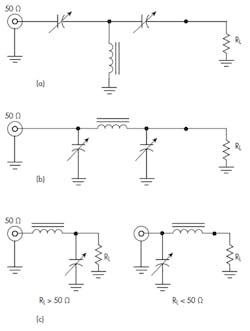
The T configuration in Figure 1a works well but has a limited range of load (RL) matching from 50 Ω to about 5 to 200 Ω. The variable capacitors do the matching. Its range can be expanded somewhat by switching in additional inductors. The circuit also is a high-pass filter. Generally low-pass filter arrangements are preferred, as they take out harmonics and other undesired signals.
The more popular tuner networks are the π and L configurations in Figures 1b and 1c. Both are low-pass filters and will match a wider range of load impedances from a few ohms to over a 1,000 Ω. Multiple variations are possible. Any of these LC circuits can be built to be manually varied so that the antenna impedance looks like 50 Ω by tuning for the lowest SWR. Note in Figure 1c that there are two L-network versions. The choice is made based on the relationship between the input impedance and output load impedance.
Two factors to consider are the insertion loss and power rating of the tuner. Be sure your components can stand up to the transmitter power that could be only a few watts to over a kilowatt. Second, the tuner will absorb some of that power. A typical insertion loss is in the 0.5- to 1.0-dB range.
A fixed network solution works fine for a given antenna and frequency of operation. If you change the frequency, the antenna impedance will change, creating a mismatch that wastes power. Therefore, you retune again. This is a common problem, as hams like to have a single antenna that can function on multiple frequency bands. A variable tuner enables that one antenna to serve most operating frequencies—it depends on the antenna, though. Readjusting the tuner allows the new conditions to be accommodated and max power is delivered to the antenna.
As it turns out, manually adjusting the tuner is a nuisance, especially if you often change frequencies. Retuning is also necessary if you change antennas. Wouldn’t it be nice if that antenna tuner could automatically tune itself to the existing load regardless of frequency? Such a thing actually exists.
An Example Auto Tuner
Paging through a recent QST magazine, a ham radio publication of the American Radio Relay League (ARRL), it becomes clear: The greatest number of ads are for antennas and automatic antenna tuners. Who would have thought? Antennas are a major problem for most hams because of the physical installation problems as well as the huge number of choices out there. And matching up the antenna to the transceiver is an ongoing common problem. The automatic tuners fit between the equipment’s 50-Ω input/output impedance and the transmission line to the antenna.
The auto Z-match unit isn’t just a convenience, but a real benefit. It means that you can get by with one antenna on multiple bands. Connecting a mismatched antenna directly to a 100-W transmitter is inviting poor operational results—and possible transmitter damage. An automatic tuner solves the problem.
Connecting the antenna to the tuner and turning on the power causes the tuner to sense any high SWR mismatch and immediately initiate changes in the capacitance and/or inductance values to optimize the Z match. The secret is how to make the L and C values change.
Most auto tuners have fixed inductors and one or more banks of capacitors that are switched by relay. Some units also may have inductors that can be switched in or out. The usual arrangement is to have a microcontroller running an impedance-matching algorithm that adjusts the C and maybe L values until a low SWR, typically <1.5 to 1 or lower, is achieved. This process usually takes the tuner several seconds or more to run through its routine and find the best match.
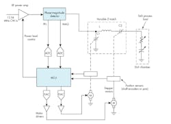
Figure 2 shows a simplified circuit of one possible solution. Most designs are some form of low-pass filter that helps minimize harmonics or other spurious emissions. This one implements a basic L network that can be switched from series L in or series L out with relay Kx. A series capacitor Cx is sometimes included to help tune stubborn loads.
The directional coupler in this solution measures the forward (FWD) and reverse (REV) or reflected power levels and produces proportional voltages that are digitized in the MCU ADCs. The control program sequences through the relay drivers in some pattern to minimize the SWR (lowest REV output). Such a tuner can usually match impedances over a range of about 5 to 1500 Ω.
High-Power Impedance Matching
One of the first automatic Z-match units that I became acquainted with was inside an Applied Materials P5000 RF plasma etcher. These complex machines are used in semiconductor fabs for etching away selected materials from wafers to make ICs. The wafer is placed in a sealed chamber. A pair of electrodes in the chamber, acting like an antenna, receive high RF power. The chamber is pumped full of a gas that will react with the material to etched away. The RF ionizes the gas, which creates a plasma that reacts with one of the wafer coatings and removes it.
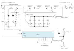
The secret to a consistent even etch is keeping the power to the chamber constant. The problem is that the impedance of the chamber keeps changing as the degree of ionization varies due to the etch process. The solution is an automatic impedance matcher. Figure 3 shows a hypothetical arrangement.
Power to the chamber can range from a few hundred watts to several kilowatts. The frequency of operation is typically 13.56 MHz, one of the ISM frequencies. Lower frequencies are used as well. An automatic tuner attaches the 50-Ω power amp output to the chamber impedance, which is a complex value usually capacitive, like 20 – j115.
To handle this power level, large wire inductors and heavy-duty capacitors with wide plate spacing are used in the tuner. The inductor is commonly fixed, though roller contact inductors have been used. Capacitors are usually driven by motors. An SWR-measuring circuit monitors the power amp output and feeds a signal back to a control circuit that continually adjusts the capacitors to maintain a suitable impedance match. Oftentimes, a Smith chart is used to define the load impedance range over which satisfactory etching will occur.
The whole thing would not work properly without that automatic Z adjustment. Sometimes, other schemes are employed. For instance, a fixed Z-matching unit may be used while the RF power output can be maintained over a narrow range by varying the RF frequency.
Design Considerations
The main obstacle in designing these circuits is having an appropriate variable capacitor or inductor. Variable inductors are difficult to build. As a result, most auto tuners use variable capacitors. The motor-driven kind are rare, except in the case of high power. Otherwise, the design can usually be implemented with banks of fixed capacitors switched in as needed. Reed relays work fine, but they require a power source. MOSFETs also can be used to perform the capacitor switching. Furthermore, PIN diodes are an option for higher-power discrete component designs.
I have not seen varicaps (varactors or voltage variable capacitors) used, but these may work in low-power applications. Some ICs with switched capacitors also could be applied in low-power situations. In all of these cases, you need a controller to operate the switches. A simple micro will do. The algorithm is the tricky or innovative part of the design.
An important factor is the SWR sensor for feedback. Most of the designs I’ve seen use a directional coupler like the one in Figure 2. This circuit measures forward and reverse power levels and develops proportional dc voltages that go to control the processor. Other techniques include an IQ detector circuit and a phase-magnitude detector.
Some ICs are available to implement the SWR measurement, too. Analog Devices makes the AD8302 gain and phase-detector IC. It needs some directional couplers, but these are usually made with short, coupled lines on a PCB. The AD8361 power-measuring detector could possibly be used. MiniCircuits also makes some circuits that measure phase.
The Smartphone Problem
Automatic Z matching has other applications. Any situation where an antenna can be detuned by nearby objects will benefit from a tuner that automatically retunes to the best conditions. This is a common problem in the modern smartphone, as the main transmit antenna is easily detuned by holding the phone in your hand, putting the phone up to your ear, or laying the phone down near some detuning object.
Detuning is also caused by the close proximity of other antennas in the phone, like those for Wi-Fi, Bluetooth, GPS, and NFC. The problem will worsen when adding multiple MIMO and 5G antennas. And with the millimeter-wave (mmWave) bands, small phased arrays will be incorporated into 5G cell phones.
In addition, detuning occurs when the phone changes frequency as it switches over to another cell site on another band. Most smartphones can cover many different cellular bands, so frequency changes are common. A fixed antenna will almost always be out of tune.
As a result, most smartphones use some form of automatic Z matching to keep the antenna efficiency high and help deliver maximum output power. The antennas in a smartphone are critical. Since they’re fixed metal devices, impedance is fixed at their resonant point, but they do have a finite bandwidth. However, their Z changes as the cellular band of operation changes. Smartphone antennas are an inefficient compromise anyway, so any tuning and matching is essential.
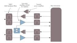
The typical smartphone antenna tuner is a capacitor network switched by MOSFETs. It’s a part of the radio-frequency front end (RFFE) that contains the LNAs, SAW/BAR filters, the linear PAs, any antenna tuning circuits, and a sophisticated switching network. Figures 4 and 5 show a typical RFFE and the block symbols. Several companies make switched-capacitor ICs for this purpose and/or complete RFFEs. The switching is controlled by the smartphone processor. A Mobile Industry Processor Interface (MIPI) is available for this application.
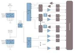
The smartphone keeps getting more complex. Thus, impedance matching circuits must also be used when more MIMO antennas are added to the handsets. The use of carrier aggregation (CA) could really challenge designers. Advanced LTE and 5G can call for up to 4 × 4 MIMO, meaning four more main antennas. Designers are still learning how to include those antennas so that they won’t interfere with one another.
As for CA, the cellular operators are beginning to combine two and sometimes more spaced-out chunks of spectrum to form a single, wide bandwidth channel capable of delivering much higher data rates. How does the RFFE deal with the wide spaced frequencies and maintain some sort of impedance match?
As Figure 4 shows, the RFFE consists of many band filters and a mix of multi-position electronic switches that can be programmed and connected as needed. All of this is combined with some Z-matching components that are switched in as needed. This RFFE is a simple one for a 3G/4G phone. Advanced 4G LTE and 5G phones will have many more filters, switches, and related components.
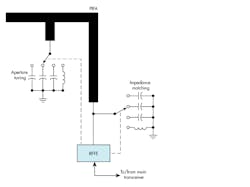
In addition to the Z-matching circuits, most smartphone antennas also use what’s called aperture tuning. Aperture tuning is another method of tuning the antenna to improve its radiation efficiency. As the antennas shrank, with more of them consequently squeezed into the handset, radiation efficiency has declined. Aperture tuning overcomes much of this problem by connecting additional capacitors and/or inductors to the antenna. Like the Z-matching components, the aperture components are switched in with electronic switches.
Figure 6 shows an example with the impedance matching and aperture tuning connections on a planar inverted F antenna (PIFA) used in cell phones. The switches are electronic, and there may be more components and/or more complex networks.
Smartphone antenna matching and aperture tuning are challenging design processes. Such complex design can be acquired rather than designed. Several choices are available—check with vendors like Infineon, Qorvo, Qualcomm, Skyworks, STMicro, and others for suitable RFFE products or reference designs.
Reference
Frenzel, Louis, RF Power for Industrial Applications, Prentice Hall, 2004.
About the Author

Lou Frenzel
Technical Contributing Editor
Lou Frenzel is a Contributing Technology Editor for Electronic Design Magazine where he writes articles and the blog Communique and other online material on the wireless, networking, and communications sectors. Lou interviews executives and engineers, attends conferences, and researches multiple areas. Lou has been writing in some capacity for ED since 2000.
Lou has 25+ years experience in the electronics industry as an engineer and manager. He has held VP level positions with Heathkit, McGraw Hill, and has 9 years of college teaching experience. Lou holds a bachelor’s degree from the University of Houston and a master’s degree from the University of Maryland. He is author of 28 books on computer and electronic subjects and lives in Bulverde, TX with his wife Joan. His website is www.loufrenzel.com.
Comment About the Article
To join the conversation, and become an exclusive member of Electronic Design, create an account today!

Leaders relevant to this article: