Boost Switching Safety with a Zero-Crossing Relay Driver
Members can download this article in PDF format.
What you’ll learn:
- What is a relay?
- What is zero voltage switching?
- How to create a zero-crossing relay driver with a simple external circuit.
A relay is a device that allows for a smaller electronic switch to control a larger mechanical switch opening and closing a contact terminal with electrical isolation between the two. They’re found everywhere, from refrigerators to elevators to amplifiers to smart meters. Since most relays involve an ac load, arcing and extra power loss at switching can be a concern if the relay opens and closes the contacts while the ac signal is around its peak. This can be prevented by switching only while the ac signal crosses zero volts, or at zero-crossing.
What’s a Relay?
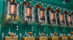
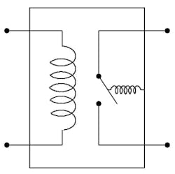
A relay consists of two isolated circuits: a controlling "primary" circuit and the controlled "secondary" circuit. The primary circuit commonly involves a transistor that controls an electromagnetic coil to pull or push a mechanical armature on the secondary circuit with its electromagnetic field (Fig. 1). It’s often powered by a smaller dc voltage supply. The secondary circuit has the contact terminal that’s opened and closed by the armature. It often involves an ac load, such as a fan, light, amplifier circuit, or a smart meter.
Zero Voltage Switching
Zero voltage switching (ZVS) aims to change the state of a relay or electronic switch at the moment there’s no significant voltage across the switching element. Nor should there be any significant conducted current at this juncture. This helps minimize wear on the mechanical contact and reduces the risk of inductive kickbacks of inductive loads.
In this application, the zero-voltage transition point of an ac power path is measured, and the signal is converted into a manageable dc square wave. This dc square wave will signal the IC to close the armature when there’s a zero-crossing condition.
ZVS also can be used to measure the frequency or phase of an ac signal. We will use this aspect of ZVS to only turn on the coil when 60-Hz ac power is being supplied to the secondary circuit with a frequency detector.
A zero-crossing voltage-detector (ZCVD) circuit that provides ZVS can be implemented in multiple ways. A focused explanation of using the GreenPAK IC for ZVS is found in AN-1210 (in this article, ZVS is referred to as ZVCD). This design uses a low-power ZCVD that consists of a half-wave rectifier feeding into a 4N25 optocoupler (Fig. 2).
In the optocoupler, the rectified ac signal turns on an LED inside that will emit light with an intensity proportional to the input signal to a phototransistor that’s also inside. When the light reaches a certain threshold, the phototransistor will turn ON. The optocoupler’s dc output is at a level manageable for a digital input.
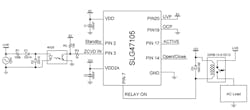
The relay on PIN7 is connected to the low side of a relay (Fig. 3). A G5NB-1A-E DC12 relay was used for this article. While RELAY ON is HIGH, the armature will open and break the connection between the electrical outlet and the ac load. When RELAY ON goes LOW, the armature will close the connection between the electrical outlet and the ac load. A flywheel 1N4148 diode is added between the poles of the coil to dissipate the back electromotive force (EMF) from the coil safely. The operating time of the relay also must be compensated for by the GreenPAK if it’s to be closed at the true zero-crossing moment. The maximum operation time for the relay is rated as 10 ms in its datasheet.
Two Agilent dc power supplies were used to supply voltage to the circuit, but a regulated voltage supply (such as using a diode ring and regulator IC) could be used to supply the 12 V and 5 V for the GreenPAK from a power outlet.
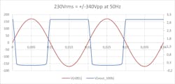
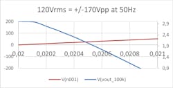
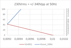
The ZCVD circuit is added externally between the ac input and ZCVD in PIN3. The output of the optocoupler has a slight delay after the true zero-crossing moment and must be compensated within this IC. The measured delay of the optocoupler was 740 µs, which doesn’t account for the input hysteresis. The graphs were derived from a simulated test of a 50-Hz input signal and the optocoupler output to estimate this delay (Fig. 4 and 5). VIHmin = 0.5 × VDD and VILmax = 0.3 × VDD. With a VDD of 3 V, the values are VIHmin = 1.5 V and VILmax = 0.9 V.
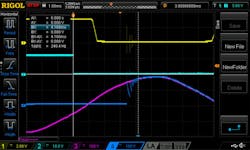
The offset we’re concerned with most is the delay between the true zero-crossing and VIHmin (1.5 V), which is about 550 µs (Fig. 6).
System Design
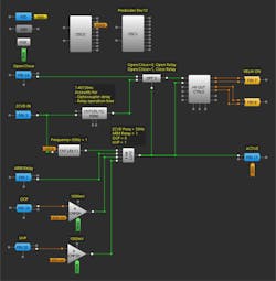
For this application, we selected the GreenPAK SLG47105. This device has four high-voltage outputs available that can go up to 13.2 V, which makes it possible to control a 12-V coil. The HV OUT CTRL0 is set to the "Half bridge" HV OUT mode and the slew rate is set to the default "slow for motor driver." PIN7 is set to "LOW side on" so that when it’s activated, it will pull down the low side of the relay to ground and turn on the relay (Fig. 7).
The 4-bit LUT0 is connected to the nRST of DFF3 and the OE of HV OUT CTRL0. The LUT (lookup table) is configured to go HIGH when ARM Relay (PIN2) is HIGH, a signal with a frequency faster than 55 Hz is sent to ZCVD IN, the overcurrent ACMP is below the threshold, and the undervoltage ACMP is above the threshold. When the 4-bit LUT0 goes HIGH, it will activate the relay driver operation and ACTIVE (PIN17) will flag HIGH.
The OCP and UVP inputs can be connected by a resistor divider to the load, supply, or another monitored IC, with the ACMP thresholds set to the correct value. In testing, OCP was connected to GND and UVP to VDD to remove their function from the circuit. The complete circuit design file can be found here.
Open/Close (PIN14) is connected to the D of DFF3 and the delayed ZCVD IN input is connected to its CLK. The nQ output of DFF3 is connected to IN0 of HV OUT CTRL0. When the DFF is activated, it will check the state of Open/Close. If there’s a HIGH on Open/Close, the circuit will signal to close the relay at a future zero-crossing of the ac line, and a LOW will signal to open the relay.
The rising edge DLY0 after ZCVD IN was set to about 7.407 ms to correct the 740-µs ZCVD delay that was measured and the 10-ms max operating time of the relay for the armature to close at true zero-crossing. This was determined because the next zero-crossing greater than 10 ms is 16.667 ms (period of 60 Hz) and the total offset to true zero crossing (operating time minus ZCVD delay) is 9.26 ms. Using the formula below, the value was calculated to be 7.407 ms (this delay can be altered to account for a different operating time):
Total Offset = Period to Next Zero-Crossing − (Operating Time − ZCVD Delay)
Test
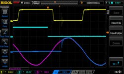
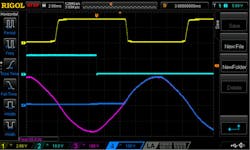
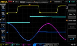
The channel allocation on the scope for these tests has Channel 1 (yellow) connected to the ZCVD IN of the SLG47105, Channel 2 (light blue) to the RELAY ON driver output, Channel 3 (pink) to the outlet signal, and Channel 4 (blue) to the relay contact.
The circuit was tested at no load with the 7.407-ms delay, but the relay did not switch at true zero-crossing (when the electrical outlet signal is at zero (Fig. 8).
To correct this, the actual operation time of the relay was measured by observing the distance between RELAY ON going Low and the relay contact settling to the same value as the electrical outlet signal. This was measured to be 4.16 ms (Fig. 9).
Using the formula above, the corrected delay was calculated as 4.793 ms. The next zero-crossing after the operating time was the half period of the power outlet (8.333 ms). The delay value of DLY0 was easily changed to reflect this in GreenPAK Designer by changing the counter value. When the circuit was retested with this new delay value, the relay switched at true zero-crossing at opening and closing (Figs. 10 and 11).
Conclusion
With some external circuitry and the correct delay, the chip was able to drive the 12-V relay at true zero-crossing. The circuit was tested at no load, so further adjustments can be made to fit its functionality with the intended load. The extra available logic allows for additional functionality to be integrated. Among the variety of applications achievable with the GreenPAK, it can provide a configurable relay driver that switches at true zero-crossing for safer and more efficient operation.
