SPST IC Switch Protects Sensors Against Overvoltage, Power-Off Faults

Many times, it’s the small, tightly focused component that does just one thing to transform a possible headache in a design into a non-issue. Or it makes the difference between a “pretty good” design that works well enough, but it can’t handle anticipated upsets, into a really good, “rock solid” design.
A good example is Analog Devices’ ADG7421F, a low-voltage fault-protection and detection switch. This dual single-pole single-throw (SPST) switch features on-resistance (RON) of just 12 Ω and provides overvoltage protection for small signals such as resistance-temperature-device (RTD) and thermocouple inputs (Fig. 1). The wide range of applications includes analog input/output modules, process-control/distributed-control systems, avionics, automatic test equipment, and even relay replacement in some cases.
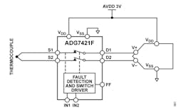
Although perhaps at first glance it seems to be “just a switch,” it protects against high voltages up to ±60 V. And due to its low-voltage supply, the ADG7421F enhances development of complete low-voltage input stages for industrial applications. It consists of two switch channels of N-channel diffused metal-oxide semiconductor (DMOS) transistors, a construction that provides excellent RON performance in a small area.
Operation is such that when no power supplies are present, the switch remains in the “off” state, and the switch inputs are high impedance. When powered, if the analog input-signal levels on input pins S1 and S2 exceed VDD or VSS by a threshold voltage VT, the switch automatically turns off and the digital fault flag (FF) pin drops to a logic low to indicate a fault.
Input-signal levels up to +60 V or down to −60 V relative to ground are blocked in both the powered and unpowered condition. The switches turn on with a Logic 1 input and conduct equally well in both directions with an analog signal range of VSS + 0.1 V to VDD − 0.55 V for a 5-V single supply.
Other noteworthy attributes include ultra-flat on-resistance of 0.005 Ω (typical), 3-kV human-body-model (HBM) ESD rating, and full latch-up immunity under any circumstances. The digital input is compatible with 1.8-V logic inputs over the full operating supply range.
Despite its diminutive size (10-lead, 3- × 2-mm LFCSP) and deliberately limited functionality, the ADG7421F comes with a comprehensive 30-page datasheet that includes tables and graphs characterizing performance under different operating conditions (e.g., temperature).
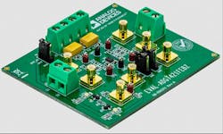
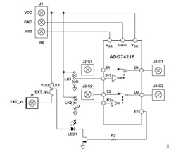
Further, to support better understanding of the switch and its functions, Analog Devices offers the EVAL-ADG7421F Evaluation Kit (Fig. 2), which allows users to connect signals and observe performance in various situations (Fig. 3). The kit is supported by its own eight-page User Guide that includes setup, operating instructions, schematic diagram, PCB layout, and bill of materials (BOM).
The ADG7421F is priced at $2.25 (1,000 pieces), and the companion EVAL-ADG7421F Evaluation Kit costs $75.
About the Author

Bill Schweber
Contributing Editor
Bill Schweber is an electronics engineer who has written three textbooks on electronic communications systems, as well as hundreds of technical articles, opinion columns, and product features. In past roles, he worked as a technical website manager for multiple topic-specific sites for EE Times, as well as both the Executive Editor and Analog Editor at EDN.
At Analog Devices Inc., Bill was in marketing communications (public relations). As a result, he has been on both sides of the technical PR function, presenting company products, stories, and messages to the media and also as the recipient of these.
Prior to the MarCom role at Analog, Bill was associate editor of their respected technical journal and worked in their product marketing and applications engineering groups. Before those roles, he was at Instron Corp., doing hands-on analog- and power-circuit design and systems integration for materials-testing machine controls.
Bill has an MSEE (Univ. of Mass) and BSEE (Columbia Univ.), is a Registered Professional Engineer, and holds an Advanced Class amateur radio license. He has also planned, written, and presented online courses on a variety of engineering topics, including MOSFET basics, ADC selection, and driving LEDs.
Comment About the Article
To join the conversation, and become an exclusive member of Electronic Design, create an account today!

Leaders relevant to this article: