Selecting Conductive Form-in-Place Gaskets
Electrically conductive form-in-place (FIP) gaskets are used as part of a flexible EMI gasketing solution for a wide range of electronic products. Many applications involve complex gasket geometry, where installation of separate elastomer, foam, or metal gaskets would be difficult and costly.
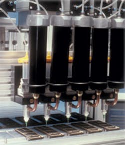
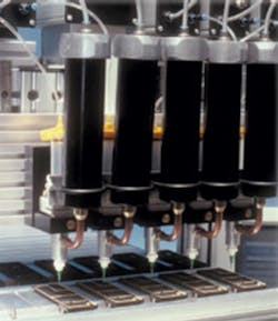
FIP EMI gaskets are made by dispensing an uncured elastomeric material on the surface of a part and curing the material in place. The material is a mixture of nonconductive elastomer, usually silicone, and electrically conductive filler particles. Gasket materials are formulated to have good adhesion to most enclosure materials without primer and to form beads in a D-shaped cross-section.
As with the more common, nonconductive FIP or cure-in-place gaskets, the uncured material is dispensed through a needle by computer-controlled, three-axis robotic equipment so gaskets with very complex geometries can be formed, positioned, and reproduced accurately. The size of the gasket bead is set by the diameter of the needle and the material flow rate, with typical gasket heights ranging from approximately 0.3 mm to 5 mm.
The gasket material usually is dispensed as a thixotropic paste cured with heat or atmospheric moisture to a relatively soft, rubbery gasket with hardness of 35 to 75 Shore A. The conductive fillers typically are metal particles or nonconductive materials like glass that are plated with a conductive metal. When cured, the gasket material has volume resistivity of 0.003 to 0.100 W??cm depending on the filler, the same resistivity range as extruded or molded conductive elastomers.
Material SelectionSuppliers of FIP EMI gasket ma-terials provide choices of conductive fillers and may offer a selection of elastomers. Most of the factors that drive the selection of FIP gasket materials are similar to those considered for all EMI gaskets, including:
- Electrical properties and shielding effectiveness.
- Mechanical properties such as compression force and compression set.
- Environmental suitability such as temperature limits and stability of electrical and mechanical properties.
- Galvanic compatibility with the enclosure materials.
- Cost of the material, processing, and curing.
- Capability to bond securely to the enclosure surface.
- Suitability of the curing method.
The only factor unique to FIP gaskets is the curing method. Heat-cure temperatures may cause problems for enclosure materials or parts so room-temperature, moisture-cured materials are widely used.
Galvanic CompatibilityGalvanic compatibility between the FIP gasket material and the enclosure materials that come in contact with the gasket is a key factor in selection of the conductive filler. Improper choice of the filler material risks rapid corrosion at the gasketed seam.
-1.48
Corrosion cannot be tolerated at an EMI gasket because it invariably increases interface resistance, reducing the effectiveness of the EMI shield. Corrosion products generally have electrical resistivity several orders of magnitude higher than the metal they came from.
Because of concerns about the effects of corrosion, the materials selected for use in conductive gaskets are resistant to corrosion in most environments. Silver is used most frequently because, in addition to being a noble metal and immune to corrosion under many conditions, silver corrosion products have relatively good electrical conductivity.
The interface between the gasket and the mating surface of the enclosure always is a concern. The enclosure is likely made from or coated with a metallic material different from the metals in the gasket. Any time there is contact between different metals, the possibility of galvanic corrosion exists.
There are three conditions for galvanic corrosion, all of which are met in almost all uses of electrically conductive gaskets for EMI shielding:
- Two electrochemically dissimilar materials. The gasket and the enclosure usually are electrochemically dissimilar because they are made of different metals.
- An electrical connection between the two materials. The gasket and the enclosure must be in electrical contact to function as part of the EMI shield.
- A path for ions to travel in an electrolyte between the materials. When parts are exposed to the atmosphere, water vapor makes a thin layer of water on all metal surfaces. How well that surface water functions as an electrolyte depends on the thickness of the layer, with thicker layers allowing easier ion movement. The thickness of surface water is roughly proportional to the humidity level. For this reason, the risk of galvanic corrosion depends on the environment that an enclosure is used in.
The proper FIP gasket material reduces or eliminates the risk of galvanic corrosion problems. The driving force for galvanic corrosion is the difference in equilibrium electrical potential between two different metallic materials in an electrolyte solution.
Many experimental measurements have shown the differences among common metals. An experimentally measured galvanic series is presented in Table 1. The metals with the highest potentials, described as noble, are unlikely to corrode. The metals with lower potentials are denoted as active.
When two dissimilar materials are in contact, the more active one will tend to have accelerated corrosion while the corrosion rate of the more noble metal will decrease. For example, copper is much more noble than aluminum, and both are stable in water by themselves, with little or no corrosion. But if aluminum contacts copper in the presence of water, the aluminum will tend to corrode rapidly while the copper will not.
The driving force for the electrochemical corrosion reaction is proportional to the voltage difference between materials. Zero or very small differences in potential will have little or no effect on the corrosion rates of either material. A large potential difference, 0.5 V or more, can accelerate the corrosion rate of the more active material by several orders of magnitude. As a result, a gasket material that is galvanically similar to the material it contacts is desirable.
The metals used in enclosures often are much more active than the conductive materials used in EMI gaskets. The use of a gasket made with silver or silver-plated copper filler in contact with an aluminum enclosure is almost certain to result in high-resistance contacts because aluminum corrodes in the vicinity of the gasket.
Galvanic TestingOne of the most common tests of galvanic compatibility is accelerated corrosion of conductive materials. A typical procedure tests gaskets compressed between two aluminum coupons by exposing them to ASTM B117 Salt Fog.
The weight loss of aluminum, a relatively active metal, is the measure of the galvanic corrosion rate. The chromated aluminum coupons corrode very little when they are in contact with nonconductive elastomer gaskets, but they can suffer large amounts of corrosion in contact with gaskets made with relatively noble metals.
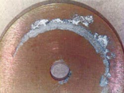
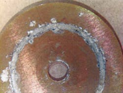

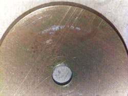
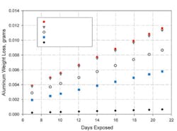
Figure 2 shows the results of one set of accelerated tests. FIP gaskets were prepared from the same silicone elastomer but with several different conductive fillers. The gaskets were dispensed on one aluminum coupon and, after curing, compressed with a second coupon. The graph shows how aluminum weight loss increased with time. Greater weight loss, or a higher slope, indicates greater corrosion of the aluminum.
Figure 3 shows aluminum coupons after 21 days of testing. It illustrates the difference between gaskets that accelerated aluminum corrosion greatly and those that had little effect on the aluminum.
The gaskets made with nickel-graphite and silver-copper fillers caused the greatest amount of aluminum corrosion, the one with nickel filler resulted in much lower corrosion, and the gasket filled with silver-aluminum caused the least.
The silver-copper material caused approximately 10 times as much aluminum corrosion as the silver-aluminum gasket. The silver-aluminum filler reacted like its galvanic potential was between those of silver and aluminum while the silver-copper behaved like its potential was between those of silver and copper.
The same effect was seen when nickel filler was compared with nickel-graphite. The nickel-graphite material caused twice as much aluminum corrosion as the nickel. The very noble graphite apparently contributes to the electrochemical properties of the nickel-graphite, making it less compatible with aluminum.
SummaryElectrically conductive FIP gaskets are widely used in shielded enclosures because they offer some unique application advantages and provide very high levels of EMI shielding. Selection of the best FIP gasket material for any application involves several factors. One of the most important selection factors is galvanic compatibility between the conductive material in the gasket and the materials it will contact in the enclosure. No one gasket material is compatible with all enclosure materials, but the proper material choice can nearly eliminate the risk of corrosion problems at gasketed seams.
About the AuthorRich Thibeau, Ph.D., a senior materials engineer at Laird Technologies, has more than 20 years experience in development of materials for electronics and EMI shielding. He holds a B.S. from the U.S. Naval Academy and a Ph.D. in physical chemistry from the University of Rhode Island. Laird Technologies, Shielding Way, Delaware Water Gap, PA 18327, 570-424-8510, e-mail: [email protected]
Return to EE Home PagePublished by EE-Evaluation EngineeringAll contents ?? 2003 Nelson Publishing Inc.
No reprint, distribution, or reuse in any medium is permitted
without the express written consent of the publisher.
About the Author
Comment About the Article
To join the conversation, and become an exclusive member of Electronic Design, create an account today!

Leaders relevant to this article: