An industry expert offers some suggestions for dealing with the challenges of testing today's high-frequency antennas.
A common solution to EMC/EMI test requirements is the rectangular anechoic chamber. However, as the frequency is lowered for operation in this type of chamber, a series of problems arises.
To begin, the size of the chamber must significantly increase. At frequencies below 500 MHz, the antennas are not as directive as those used at microwave frequencies. To get a high directivity at those frequencies, horns would have to be very large. Since antennas with lower directivity must be used, the absorber on the sidewalls, ceiling, and floor has to be thicker, and a larger structure is needed to accommodate the thicker material.
The tapered-chamber idea came about to solve the drawbacks of rec-tangular chambers at low frequencies. In the tapered chamber, the specular reflections are not eliminated but instead used to obtain a far-field condition at the location of the antenna under test.
The tapered geometry locates the specular region close to the source. Image theory shows that the images of the source antenna are very close to the actual antenna. This creates a virtual source antenna array. Figure 1 shows how the tapered geometry is used to create this source array that illuminates the quiet zone (QZ) with a quasiplane wave.
Figure 1. Tapered Chamber Layout Showing Quiet Zone
Most of the knowledge used in the design of tapered chambers has been gained using an empirical approach. The theoretical basis of the design is ray-tracing techniques and image and array theories. The lowest frequency of operation and the QZ level are going to be determined by the back-wall absorber.
The required QZ size determines the height and width of the chamber. While it is desirable to have about two wavelengths between the QZ edge and the tips of the absorber, as a rule of thumb, the QZ can be one-third the width and height of the chamber.
As is the case with a rectangular chamber, the size of the test area is determined by the range equation:
Once the cubical or rectangular section of the chamber has been set based on the size of the QZ, the tapered section must be designed. The angle of the taper depends on the frequency range of the chamber. From Figure 1, it is clear that the source of the chamber is an array of sources. Array theory shows that to avoid ripples in the pattern at the test area the elements must be closer to each other to approximate the pattern of an isotropic radiator.
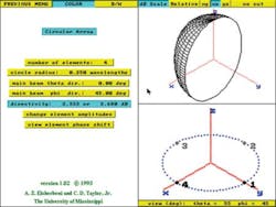
When four identical isotropic sources are brought close together, they produce an array factor isotropic in nature (Figure 2). For this reason, the far field of the source antenna of the chamber will be close to the actual radiation of the antenna in free space. Remember that the pattern of an array of antennas is the multiplication of the array antenna factor by the pattern of the elements.
This isotropic array factor remains as the number of elements in the array increases, as is the case in a conical feed section. If the feed section is pyramidal in section, the same is found: As the elements are brought closer together, the pattern is smoother in the direction of the test area.
The antenna array theory suggests that smaller separations are better if the goal is to reduce the ripples in the pattern. The array theory also shows that, by attenuating the images with respect to the central source, the separation requirement can be relaxed. This attenuation can be accomplished by placing some absorbing material at the feed location.
Finally, experience confirms that angles under 28• are needed for operation up to 18 GHz. For even higher frequencies, the chamber can be used as a rectangular chamber if the absorber layout has been set to allow for this operation; that is, specular areas have been set at the correct locations.
Having determined the rectangular section of the taper chamber, the length of the taper, found by using simple geometry and trigonometry, is given by:
An Example
A typical test-chamber specification required a 6-ft QZ, a maximum cross section of 20 ft • 20 ft, and an overall length of no more than 45 ft. The first requirement we need to satisfy is the 6-ft QZ diameter. Since the width and height of the chamber should be three times the QZ diameter, a 20-ft • 20-ft cross section is suitable.
The goal is to use this chamber down to 500 MHz. The specified 45-ft maximum chamber length exceeds the minimum 43-ft distance found from the range equation, so range length does not seem to be an issue.
In tapered chambers, the back-wall absorber treatment controls the reflectivity in the QZ. Unlike rectangular chambers, the specular reflection from the sidewalls is being used to create the plane-wave behavior in the QZ area. Table 1 lists the design goals for the chamber.
| Frequency | Desirable Goal |
EHP-36 Performance |
| 500 MHz | -40 | -40 |
| 2 GHz | -40 | -45 |
| 4 GHz | -40 | -50 |
| 8 GHz | -40 | -55 |
| 12 GHz | -40 | -55 |
| 18 GHz | -40 | -55 |
| 40 GHz | -40 | -55 |
The back-wall absorber must be ETS type EHP-36PCL or CRV-23PCL, which has a reflectivity of better than 40 dB at 500 MHz. CRV-23 would have a performance equal or better than EHP-36, but CRV-23 is 1 ft less in depth and will allow a reduction in the overall chamber length.
Performance at higher frequencies is not an issue. For materials used in absorber manufacturing, the dielectric constant is defined as:
The propagation constant is given by:
This behavior affects the reflectivity of the absorber because, assuming a pyramid with a smooth change in wave impedance along the length of the absorber, the reflectivity is related to the attenuation in the absorber. The reflectivity is given by:
where: x = the height of the absorber
So, for a given pyramidal-type absorber and assuming the properties do not change too much with frequency, then as frequency increases, wavelength decreases, attenuation increases, and reflectivity decreases.
This is a theoretical approach, and it suggests that in a perfect world the absorber performance will increase with frequency. In reality, the performance levels off at about -55 dB. Experience has shown this to be the case for most pyramidal microwave absorbers. Only at 90 GHz does the performance degrade, and this is due to the paint covering. By leaving the front of the absorber unpainted, the absorber can be used at higher frequencies.
The sidewalls of the rectangular section of the tapered chamber will be treated with 18 absorbers. This leaves 17 ft of space from absorber tip to absorber tip in the rectangular section of the tapered chamber. Assuming a taper angle of 28 for good high-frequency operation, we have a tapered section 40 ft long. It is desirable to have at least a cubical rectangular section. The depth of the section should be at least as large as the width or height. That's why the minimum overall length of the chamber must be 60 ft, not the desired 45 ft.Figure 3 shows the typical absorber treatment used in tapered chambers. Pyramidal absorbers will be used in the rectangular area and in part of the tapered section. This layout helps at the very high frequencies when the chamber is behaving like a conventional rectangular chamber.
Wedge-shaped material is used on most of the tapered section, reducing in thickness from the 18 in. of the pyramids to the thickness of the material located in the feed section. At the apex, a conventional lossy foam block is used.
Although it is impossible to model the entire anechoic chamber using the finite-elements technique, ETS-Lindgren has used its finite-element software package to analyze only the feed section of tapered chambers. Figure 4 shows the feed section of a tapered chamber at different frequencies. This finite element analysis tool is used in addition to the tapered-chamber calculations performed using ray-tracing techniques. Table 2 shows the expected performance of a tapered chamber to accomplish the requirements of the customer.
| Chamber Construction |
Configuration: tapered chamber Dimensions: 20-ft • 20-ft • 20-ft cube with 40-ft long taper Intended Use: antenna measurements |
|||
| Shielding | Series 81 | |||
| Anechoic Materials |
Receive End Wall: EHP-36PCL pyramidal, flame-retardant absorber Taper Wall: EHP-18WGCL wedge, flame-retardant absorber tapering down to 5• LFB Ceiling, Floor and Side Walls: combination of EHP-18PCL absorber, around the QZ Walkways: WW-12PCL rigid walkway |
|||
| Anechoic Performance |
Frequency | Source Antenna Directivity |
Quiet Zone Reflectivity Level |
Guaranteed Reflection Level |
| 0.5 GHz 1 GHz 2 GHz 4 GHz 8 GHz 12 GHz 18 GHz 40 GHz |
15 dB 15 dB 15 dB 15 dB 15 dB 15 dB 15 dB 15 dB |
<-43 dB <-46 dB <-48 dB <-55 dB <-55 dB <-55 dB <-55 dB <-55 dB |
-40 dB -43 dB -45 dB -53 dB -53 dB -53 dB -53 dB -53 dB |
|
| Anechoic Parameters |
Quiet Zone Volume: up to 6-ft sphere Path Length: up to 45 ft |
|||
| Acceptance Testing |
Type: free-space VSWR test at 7 frequencies as requested by the customer Frequencies: 0.5 GHz, 2 GHz, 8 GHz, 12 GHz, 18 GHz, 26.5 GHz, 40 GHz Antenna: SGH high-gain antennas to probe the QZ Polarizations: horizontal and vertical |
|||
This approach provides the performance that the customer requires. However, there are limitations with the tapered chamber. The feed section must be specially designed to accommodate different types of antennas with at least 15 dB of gain.
Broadband horns are not always suitable because, as the frequency increases, the antenna appears to be electrically farther away from its images, and no longer does the array factor appear to be an isotropic array factor. Nevertheless, with the proper numerical tools, the feeds can be designed so that the tapered chamber will perform as expected.
About the Author
Vicente Rodriguez-Pereyra is an RF and electromagnetics engineer at ETS-Lindgren. Previously, he was a visiting assistant professor in the electrical engineering and computer science department at Texas A&M University-Kingsville. Dr. Rodriguez attended the University of Mississippi where he obtained a B.S.E.E. and a master's degree and a doctorate in engineering science with emphasis on electromagnetic theory. He is a member of the IEEE and its MTT and EMC societies and the Applied Computational Electromagnetic Society. ETS-Lindgren, 1301 Arrow Point Dr., Cedar Park, TX 78613, 512-531-6400, e-mail: [email protected]
All contents • 2004 Nelson Publishing Inc.
No reprint, distribution, or reuse in any medium is permitted
without the express written consent of the publisher.


