Using Radar Amplifiers for Automotive RF Imminity Tests

It is vitally important that cars driving past airfields or close to radar weather stations do not malfunction when illuminated by a radar beam.
Over the last decade or so, powerful radar systems have been installed at airports and at elevated points overlooking aircraft routes. This national radar network upgrade provides enhanced air safety through improved aircraft location capability and a new capacity to monitor the formation and progress of storms.
Plainly, this makes for safer air travel, but with today's cars chocked full of electronic circuits, the modernized radar network presents a new hazard. The auto industry has addressed this hazard by changing automotive RF immunity standards to include high-stress tests at radar frequencies.
Upgraded National Radar Network
There are two basic types of radar used in air-traffic control: primary radar and secondary radar. Primary radar sends out a pulse and gathers information from the echo. Secondary radar, based heavily on military friend-or-foe technology, transmits interrogation pulses, and a transponder in the aircraft sends back information on its identification and status.
Primary radars need to generate far greater amounts of power since the pulse has to complete a return journey. And due to the fact that the incident pulse is scattered by the aircraft in many directions, the radar antenna captures only a tiny amount of the total reflected energy. This need for much higher power makes primary radar the greater threat to car electronics.
Changes to the national network include the installation of two primary radars: one in the L-Band (1,215 MHz to 1,400 MHz) and one in the S-Band (2,700 MHz to 3,000 MHz).
Air Route Surveillance Radar Model 4
Developed under a joint FAA and DoD initiative for air-traffic control and air defense purposes, the ARSR-4 has a range of 250 nautical miles, a 60-ft diameter antenna, and a 65-kW klystron amplifier and operates over 1,215 MHz to 1,400 MHz. The FAA uses the 1,240-MHz to 1,370-MHz portion of the band; the remaining portions are allocated to the DoD. The ARSR-4 also provides weather information to the FAA and the National Weather Service.
WSR-88D
Although the system number WSR-88D may be unfamiliar, many people recognize Next Generation Weather Radar (NEXRAD) as a key source of information commonly used in the daily weather forecast. NEXRAD is a Doppler radar capable of detecting not only the existence of weather phenomena such as storms but, most importantly, it also has the capability to measure wind shear.
With a range of 250 nautical miles, the WSR-88D operates over 2,700 to 3,000 MHz and is powered by a 750-kW klystron. The 2,900-MHz to 3,000-MHz segment is used for weather information by the FAA and the National Weather Service. The remainder of the band is used for radio navigation and by DoD surveillance radars.
Action by the Auto Industry
In response to the threat posed by the new national radar network, car manufacturers have upgraded EMC test procedures to include testing for immunity to simulated radar fields. Figure 1 shows the added bands and stress levels. The test bands added are 1,200 MHz to 1,400 MHz (L-Band radar plus a slight margin) and 2,700 MHz to 3,100 MHz (S-Band radar plus a slight margin).
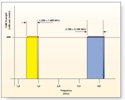
The stress level stipulated for both bands is 600 V/m at a distance of 1 meter. General Motors released test standard GMW3097 revision 4 in December 2003 and Ford the ES-XW7T-12A278-AC in October 2003. Components and subsystems supplied to these auto industry giants now must comply with the amended standards.
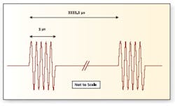
The applied test pulses are shown in the time domain in Figure 2a and in the frequency domain in Figure 2b. The pulses are 3 's long and produced at a repetition rate of 300 Hz. This equates to a low duty cycle (ratio of time on to time off) of 0.1%. A single burst of 50 pulses is applied once a second during the test. The test is repeated over a predetermined range of spot frequencies across each radar test band.
Generating test fields of 600 V/m at these high frequencies would seem to be a formidable challenge. In real radar systems, klystrons produce tens or hundreds of kilowatts. Using klystrons for test purposes would be excessive and cost prohibitive.
Fortunately, there are two factors that aid the EMC industry in achieving these test fields. First, the higher the frequency, the more efficient antennas become at converting the RF signals to RF fields. For instance, high-gain microwave horn antennas need only 300 to 500 W to achieve 600 V/m at a 1-meter distance. Secondly, short pulse width and low duty cycle mean that the average power rating of the amplifier can be small.
The main types of amplifier available to generate the simulated radar fields are continuous wave (CW) traveling wave tube amplifiers (TWTA), pulsed TWTA, and solid-state Class C amplifiers.
Traveling Wave Tube Amplifiers
In a traveling wave tube (TWT), the RF signal makes its way along the main axis of the tube via a tightly wound transmission line called the helix. An electron beam passes directly along the tube through the center of the helix.
The beam has a direct path to the end of the tube while the RF, although traveling close to the speed of light, has to traverse around the many turns of the helix to get to the output. This slowing of the RF signal through the tube allows interaction with the high-energy beam, and amplification of the RF signal takes place at the expense of the power in the beam.
Two basic types of helix TWTAs are manufactured: CW and pulsed. As implied in the name, CW means that, during transmission, the signal is present all the time. Pulsed TWTAs have a control grid fitted allowing the beam to be switched on and off so that during transmission the RF output is pulsed.
Owing to the low average dissipation of a pulsed tube, for the same thermal design, the output power capability can be far greater than its CW equivalent. Typically, if a CW amplifier has a maximum output power of 200 W, its pulsed equivalent will have a maximum output power of 2,000 W.
Thirty years ago, TWT amplifiers were manufactured to match the traditional bands of 1 to 2 GHz, 2 to 4 GHz, 4 to 8 GHz, 8 to 12.4 GHz, and 12.4 to 18 GHz. The quest to provide 1- to 18-GHz solutions with a lower amplifier count, coupled with the steady encroachment of solid-state technology at the lower frequencies, has shrunk many product lists to three bands: 1 to 2.5 GHz, 2.5 to 8 GHz, and 8 to 18 GHz.
Solid state now offers 1 to 2 GHz at 1 kW with superior performance. As a result, the 1- to 2-GHz TWTA has become a dying breed. However, keep in mind that TWTAs outperform solid state in bandwidth and power above 4 GHz, and they are destined to remain a vital RF component in many applications for the foreseeable future.
Using CW TWTAs to Generate the Test Fields
Possible pairs of CW TWTAs are 1 to 2 GHz + 2 to 4 GHz and 1 to 2.5 GHz + 2.5 to 8 GHz. Depending on the microwave horn antenna gain characteristic, the power required will be around 250 to 300 W.
There are two issues with this solution: band utilization and harmonic noise. For the 1- to 2-GHz + 2- to 4-GHz combination, only 600 MHz of the total 3,000 MHz actually is used, only 20%, yet you pay for the capability to amplify across the complete 1- to 4-GHz band. For the 1- to 2.5-GHz + 2.5- to 8-GHz solution, the frequency utilization is worse.
TWTAs have atrocious harmonics when operated at or close to the lower band edge as is the case with the L-Band amplifier. The power in the first harmonic often is equal to or greater than the power at the fundamental frequency.
As the fundamental frequency moves away from the band edge, the harmonics improve but still are at a comparatively high level compared to solid-state amplifiers. When the fundamental moves up to the high end of the band, the first harmonic falls out of band, and the harmonic power drops to a more acceptable level.
Using Pulsed TWTAs to Generate the Test Fields
This requires two pulsed TWTAs, one for each radar band.
The higher power available from pulsed TWTAs makes for significant power overhead, which can be especially useful when dealing with reflected power.
A TWTA running at a fraction of its forward-power capability can work into relatively high mismatches. This can best be explained by example:
If a TWTA can produce 1,000 W of forward power but actually is only required to output 250 W to the antenna, then if a mismatch causes 50% of the power to be reflected back into the amplifier, the amplifier must tolerate 125 W of reflected power. To a 1,000-W amplifier, 125 W represents only 12.5% of its forward-power capability, and this can be absorbed without damage.
If, however, the amplifier was required to deliver 1,000 W to the antenna, then 50% reflected power would equate to 500 W. This would damage the amplifier if protective circuits were not in place. Since pulsed TWTAs are broadband devices, severe underutilization of the available bandwidth also applies here.
A recent introduction to the market is a single-band solution using a single pulsed TWTA. This is achieved by detuning a 1- to 2.5-GHz amplifier so it produces pulsed power over 2,700 MHz to 3,100 MHz. The intended advantage is to remove the need to change amplifiers when testing the two radar bands.
If the device under test proves susceptible to these conditions, was the failure caused by the intended test field, the unintended harmonic field, or due to the simultaneous application of both fields? The harmonic power could be filtered out with an absorptive high-power low-pass filter, but this must be removed to complete the S-Band test. As a result, the main advantage of the single amplifier solution is wiped out.
An additional and important concern with procurement planning is the increased possibility of delayed delivery due to the extra risk involved with special tuning. Detuning a TWT is a black art fraught with danger for the TWT. If the beam becomes defocused during the exercise, the helix can quickly be destroyed.
A final note on the use of TWTAs: Periodically, high-voltage arcs will be created inside the tube. When this happens, large amounts of power can appear at the input connector. To prevent damage, an isolator should be fitted between the signal generator and the TWTA.
Class C Solid-State Amplifiers
In response to the needs of civil and military radar manufacturers, single bipolar transistors capable of producing 300 W of pulsed RF power have been developed for the more common radar frequency bands. The devices are designed specifically for class C operation.
Class C displays a highly nonlinear response. However, a tuned output circuit, commonly referred to as a tank circuit, suppresses harmonic noise, allowing only the wanted signal to be amplified. The transistors run on an abnormally high DC voltage supply and remain biased off until the RF input signal comes along.
Under these conditions, the transistor can produce high-power RF for a short duration without heat damage occurring to the junction. This remains true as long as the average dissipation in the junction is kept down. Typical pulse widths are 100 's, typical duty cycle is 10%, and many kilowatts of output power can be achieved by power combining transistor outputs. The harmonic performance is excellent.
These amplifiers are used in real radar systems, making them suitable candidates for creating radar test fields. The bandwidth utilization is 100%, and they are available with output circulator protection, allowing operation into high voltage standing wave ratio (VSWR) loads.
But there is a major drawback. The output power level cannot be adjusted. This is a serious restriction since, if the output power cannot be adjusted, the 600-V/m field strength cannot be set. With CW and pulsed TWTAs, simply changing the input power level sets the output power. This is not the case with class C solid-state amplifiers.
Limited output power control can be achieved by varying the Vcc voltage across the transistor. This will provide only about 4 dB of turndown capability, but for a 500-W amplifier, this equates to an adjustable power range of 200 W to 500 W. This is enough to set the 600 V/m with suitable microwave horns.
Two amplifiers are required, one for each band. Because these amplifiers are used in real radar systems, frequency ranges covering the exact bands specified by the new test procedures are readily available. The EMC software would need to control the output power of the amplifier remotely, such as via an IEEE 488 interface. Most EMC software programs are able to control several test instruments, so interfacing with the test program should not be a serious issue.
System Calibration
Calibration of the system under radar-type pulse conditions presents a significant departure from normal for two reasons. Firstly, the short-duration pulses result in short-duration fields. Most field probes are designed for CW use and do not have a fast enough response time to measure the field strength.
Secondly, even with a fast-response field probe, the probe output is a composite reading of all the fields produced by the antenna, intentional or otherwise. So if a TWTA produced 200 W at the fundamental frequency and 200 W at the first harmonic frequency, there would be no way of knowing that a major portion of the measured field strength was created at a bogus test frequency.
One way to calibrate the system would be to use an identical horn antenna at the prescribed distance and a receiver to measure the field strength. The signal would need to be suitably attenuated to avoid damaging the receiver input circuits.
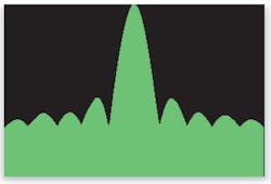
Due to the pulsed nature of the signal, the receiver would display a sinc(x) function, such as sin(x)/x shown in Figure 2b. Sinc(x) functions would be found centered at the fundamental frequency and at the harmonic frequency. The field strengths then could be deduced from the amplitude of the displayed waveforms.
Conclusion
Two main technologies, TWTA and class C solid state, are available for generating the new radar test bands. TWTAs are wasteful in terms of band utilization and have a serious harmonic issue if used near the lower band edge.
Class C solid-state radar amplifiers are used in real radar systems and provide exact coverage of the two new test-band frequencies. With isolator protection, they are VSWR tolerant and display excellent harmonic performance.
Class C solid state has a weakness because output power control does not come as standard, so remote control of the Vcc would need to be added to make them suitable for this EMC application. However, serious consideration should be given to working with radar amplifier suppliers to add this feature to these standard radar amplifiers.
About the Author
Thomas Mullineaux, the chief writer at HighTechWriter, is an RF engineer with 15 years experience in leading design teams. HighTechWriter, 3332 Florista St., Los Alamitos, CA 90720, 562-400-4501, e-mail: thomas_ [email protected]
FOR MORE INFORMATION
on updates to EMC testing at Ford Motor Company
www.rsleads.com/503ee-215
About the Author
Comment About the Article
To join the conversation, and become an exclusive member of Electronic Design, create an account today!

Leaders relevant to this article: