Learn more about what's involved in testing UWB devices to the applicable regulations.
Ultrawideband (UWB) technology provides low-cost communications and measurement capabilities for a number of applications including short-range data exchange in excess of 100 Mb/s, imaging through walls and into the ground, and automotive speed and distance reporting and control.
The technology for generating UWB signals generally is simple and inexpensive. Short electrical pulses on the order of picoseconds or nanoseconds in duration are directed through band filtering to an antenna. The narrow pulses, which may be modulated in time position, repetition rate, pattern, or polarity, generate a wide spectrum of emissions whose bandwidth is inversely proportional to the duration of the pulse.
Because UWB transmissions have the potential to interfere with many licensed and unlicensed radio services, restrictions must be placed on the UWB signal power depending on the specific application. In the United States, the FCC has established Subpart F of Part 15 to govern unlicensed UWB devices. The rules were established in 2002 after careful investigation of interference issues such as multiple UWB transmitters and coexistence with global positioning satellite (GPS) receivers.
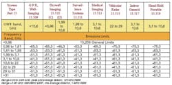
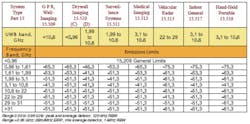
Table 1. FCC UWB Emissions Limits
The standards include procedures and limits similar to FCC Part 15, but they have not been harmonized to the European Union (EU) Radio and Telecommunication Terminal Equipment (R&TTE) Directive. As a result, the standards are not widely acceptable for demonstrating equipment compliance in the EU. Outside of the United States and the EU, no other UWB standards have been established yet.
UWB Testing
There is no single set of FCC emissions limits for all UWB devices. There are general requirements in section 15.521, which includes the 15.209 limits below 960 MHz and a 0-dBm equivalent isotropically radiated power (EIRP) peak emissions limit for all UWB devices operating above 960 MHz. Otherwise, each category of UWB device has its own emissions limits. The restricted band limits of 15.205 do not apply to UWB devices.
Before testing begins, the engineer must be sure that the appropriate set of limits is being applied to the UWB transmitter. An incorrect choice of limits may not be an easy error to correct after testing has been completed. Moving from one UWB device type to another can involve different upper frequency ranges, antennas, and low noise amplifier (LNA) choices.
In addition to 50 MHz for peak EIRP, the FCC has designated three different measurement bandwidths for UWB devices: 1 kHz for emissions in the GPS receiver bands. 120 kHz for emissions in the 30-MHz to 960-MHz range.1 MHz for emissions above 960 MHz.
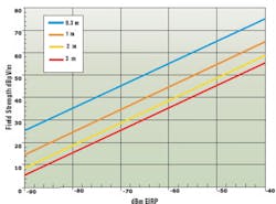
The use of dBm EIRP as a limit may be unfamiliar. The FCC provides a formula for converting from field strength at 3 m to dBm EIRP:
dBm EIRP = dBµV/m – 95.2
For other test distances, Figure 1 relates field strength to values in dBm EIRP. Spectrum analyzer readings may be converted between dBµV and dBm using the formula:
dBm = dBµV – 107rms Average Detector: 1-MHz RBW, above 960 MHz except in GPS bands where it is >1 kHz, 1 ms or less averaging time. Trace averaging is not used. The <1-ms averaging time is achieved by selecting a sweep time on the spectrum analyzer at least as fast as 1 ms times the number of screen data points or bins.
An rms average detector was selected by the FCC for UWB emissions because it most accurately reflects the interference potential of the signals. Spectrum analyzers are readily available with rms detectors. An alternative to the rms detector is provided in procedure (3) in Appendix F of the UWB First Report and Order (ET Docket No.98-153).Peak Emissions in 50 MHz: This measurement is centered on the frequency at which the highest emissions occur in the UWB band used. Most spectrum analyzers are not capable of a 50-MHz RBW so the FCC has provided a formula for redefining the peak emissions limit of 0-dBm EIRP in terms of the RBW actually used:
EIRP limit in dBm =
20 log10(RBW used in MHz/50)
The actual RBW used must be >1 MHz and <50 MHz and typically 3 MHz. Any RBW larger than 3 MHz will require additional technical justification. EIRP is converted to field strength in dBµV/m using the relationships shown in Figure 1 and the underlying formula.
Test engineers will recognize that the relationship between the spectrum analyzer average display level and the RBW for broadband emissions is proportional to 10 log10 (RBW) rather than 20 log (RBW) as reflected in the FCC's UWB formula. The FCC formula is based on the conservative justification that changes in the peak levels follow the square of the change in the resolution bandwidth.
Every UWB device must undergo all three measurement types to demonstrate compliance with the FCC rules. In combination with high operating frequencies and possibly unusual test setups, they present an interesting challenge.
Equipment Requirements
UWB testing requires the same types of equipment common to most radiated emissions tests: receiver for quasipeak measurements, spectrum analyzer for measurements above 960 MHz, measurement antennas, preamplifiers, antenna mast, cables, and a support table for small devices. However, UWB testing can demand some unfamiliar performance requirements from this equipment.
Spectrum Analyzer
In addition to an rms detector, the spectrum analyzer should have a low noise floor. A typical good specification would be -140 dBm using a 10-Hz RBW over the range of 10 MHz to 3 GHz. This translates to a -90-dBm or 17-dBµV noise floor using a 1-MHz RBW. For UWB devices operating above 10 GHz, the spectrum analyzer must accommodate external mixers to extend the measurement range to 100 GHz.
Antennas
Two measurement antenna types generally will be necessary. The FCC recommends a log-periodic antenna below 960 MHz although other types of measurement antennas such as biconicals may be used. For radiated measurements above 960 MHz, a broadband horn antenna or a broadband log periodic antenna can be used.
Owing to the low UWB signal levels and emissions limits above 1 GHz, the high antenna factors of broadband horns may result in too much signal loss to overcome with a practical selection of preamplifiers. To obtain an adequate signal margin above the measurement noise floor, it could be necessary to use a series of standard-gain horn antennas with lower antenna factors.
Preamplifiers
It is common to use a preamplifier for radiated emissions measurements below 960 MHz. For UWB testing, it will be necessary to use one or more wideband LNAs to measure radiated emissions above 960 MHz, especially in the GPS frequency bands and above.
Satisfactory LNAs may be packaged instruments or modules, but they will provide individual gains of at least 30 dB with noise figures of 2 dB or less each over the frequency bands of 1 to 26 GHz and 26 to 40 GHz if measurements as high as that are required. If the frequency bands are subdivided into smaller spans, more preamplifiers will be needed but each one can have a lower noise figure.
Ambient emissions can cause preamplifier overload. In the presence of interfering signals, it may be necessary to use filters ahead of the preamplifiers. Filter attenuation of the wanted signal must be known.
Harmonic Mixers
Harmonic mixers extend the measurement frequency range of the spectrum analyzer above its direct input limit of 26.5, 40, or 50 GHz. Harmonic mixers may be two-port or three-port depending on the configuration of the spectrum analyzer. The measurement horn antenna is mounted directly onto the mixer to minimize cable loss at the very high microwave frequencies.
Mixer loss of typically 20 to 30 dB must be added to the antenna factor to derive the measured field strength. The combination of mixer loss and antenna factor may be as high as 50 or 60 dB, making detection of low-level UWB signals difficult.
Cables and Connectors
Low-loss instrument cable assemblies should be used at frequencies above 1 GHz for linking the measurement antenna, preamplifiers, filters, and the spectrum analyzer. These cable assemblies and any separate adapters should be rated for the maximum measurement frequency and provide minimum attenuation. SMA and Type N connectors can be used to 18 GHz; Type K or 2.9-mm connectors are satisfactory to 40 GHz.
Sharp bends or kinks in any high-frequency cable can cause unaccounted attenuation. The complete measurement chain should be validated for continuity.
Support Table
There is experimental evidence that reflections from an emitter on a wooden support table can result in measurement errors approaching 6 dB at frequencies above 1 GHz. The use of low-density plastic materials in the support table will reduce such spurious reflections.
Part 2
Part 2 of this article focuses on the procedures required for testing UWB, the special challenges that may be encountered, and recent developments issued by various ruling bodies around the world. It will appear in EE's June issue.
Defining UWB In the absence of clear competing definitions, we can use the definition of a UWB transmitter included in FCC 15.503(b): An intentional radiator that, at any point in time, has a fractional bandwidth >0.20 or a UWB bandwidth >500 MHz regardless of the fractional bandwidth.The term fractional bandwidth is further defined in 15.503(c) in terms of the highest (fH) and lowest (fL) frequencies at which the radiated emissions are 10 dB below the maximum radiated emissions. For fractional bandwidth, the formula is the following:
2(fH – fL)/(fH + fL)Two other terms are defined in the FCC UWB rules. Center frequency is the average between fH and FL: fC = (fH + fL)/2 The value of fC determines the highest frequency to be measured. The highest measured emissions occur at fM. Note that fM and fC are not necessarily the same.Not to be confused with the figure of at least 500 MHz for UWB bandwidth, the FCC recently introduced the term wideband into two new sections of Part 15:
• 15.250: 50-MHz bandwidth at the -10-dB points for 5,925-MHz to 7,250-MHz wideband systems.
• 15.252: 10-MHz bandwidth at the -10-dB points for wideband vehicular radars in the 17-GHz and 25-GHz bands.
These new Subpart C wideband rules should not be confused with similar UWB applications in Subpart F.
Attributes of UWB
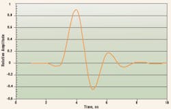
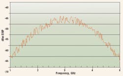
The narrow pulses used to generate UWB emissions result in a radiated field that typically varies slowly over the -10-dB bandwidth of hundreds of megahertz to several gigahertz. Figure 2a shows a typical UWB pulse and Figure 2b the resulting emissions spectrum.
The very nature of UWB emissions presents testing challenges:• Emissions levels and limits are very low. The combination of antenna gain and spectrum analyzer noise floor may require the use of one or more LNAs to preamplify the signal to a measurable level. The LNA brings additional considerations such as noise figure, bandwidth, and saturation. Identification of spurious emissions levels can be more difficult if the test site is exposed to ambient fields although there are few other transmitters operating in UWB bands so far.
• Emissions frequencies can be very high. Except for 15.510(c) imaging systems, all other UWB bandwidths are above 1 GHz; vehicle radar bandwidths are above 22 GHz. Special procedures must be used to identify and measure any narrow emissions lobes from the transmitter and extra precautions taken in the selection and handling of antennas, measurement cables, connectors, and the support table.
About the Author
Roland Gubisch, Ph.D., chief engineer for EMC and telecommunications at Intertek ETL SEMKO, has served as an engineering manager and quality manager since joining the company in 1990. Outside of Intertek, Dr. Gubisch is a member of the IEEE, NFPA, and IEEE Communications and EMC Societies and previously was the vice president of the U.S. Council of EMC Laboratories (USCEL) and
a delegate to TIA subcommittee on harmonization of United States and Canadian telecom regulations. His education includes a B.S.E.E from Northwestern University and a Ph.D. in physiology from Cambridge University. Intertek ETL SEMKO Division, 70 Codman Hill Rd., Boxborough, MA 01719, 800-967-5352, e-mail: roland. [email protected]
FOR MORE INFORMATION
on FCC Part 15 Subpart F
www.rsleads.com/505ee-202
