
Instruments
With today's focus on higher speeds and wider bandwidths, it often is helpful to revisit basic yet critical design considerations. As a refresher topic on grounding techniques, we present this update of an article that appeared in the January 2002 issue of EE-Evaluation Engineering.Make sure all your equipment is connected to a good EMI ground.
As technological and process requirements change, the demands for the quality of grounding change, too. Simply complying with the safety standards and conventional ESD grounding standards no longer is enough. We need to examine ground from a different perspective electromagnetic interference.
When electromagnetic fields affect normal operation of equipment, EMI is present. Often, the electromagnetic environment is aggravated by poor installation or maintenance of equipment. In the last several years, EMI-related issues have become increasingly important due to the higher susceptibility of computer-controlled equipment operating at higher clock frequencies.
Let's examine two identical tools, such as an IC handler and a photolithography scanner (stepper). As seen in Figure 1, one tool is connected to ground by a short, wide, braided wire, the other via a long, coiled, thin-gauge wire. From the safety and ESD points of view, grounding of both tools meets the standards and is considered adequate for its operation.
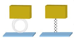
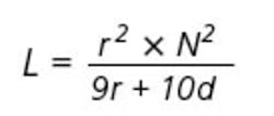
But, are these two tools grounded equally well? Existing standards specify properties of grounding mostly at DC and 50/60 Hz. At higher frequencies, long, coiled wire forms an air-core inductor whose inductance is calculated as
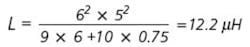
As an example, if the extra ground wire is coiled to 12″ dia and has five turns and the coil is 0.75″ long, inductance of this coil will be
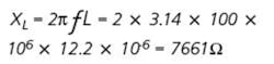
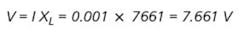
At a 100-MHz frequency, the impedance of this coil will be
What if the ground wire is not coiled but simply too long? Inductance of a straight wire at high frequencies can be calculated as
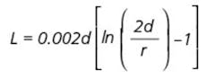
A common 10-m ground run of 12-gauge solid wire has self-inductance at high frequencies of


Is 1 mA of high-frequency current unreasonable to expect in the production environment? An ESD event, such as when a worker touches a tool's enclosure after walking and consequently charges himself, could easily reach several amperes. High-frequency current flowing to ground caused by normal operation of equipment such as electric circuits, solenoids, or motors can easily reach tens of milliamps.
When a ground bounce occurs, the ground voltage on the tool may be significantly different from the one on the connected computer or another tool. This can easily garble the communications between the tool and a computer, and the tool can stop working.
Even worse, the tool can begin to do something completely unexpected. For example, a robotic wafer handler in a front-end semiconductor facility might toss an expensive wafer on the floor because of an EMI event. Such problems could be very difficult to diagnose. Too many tools grounded to a single point may result in excessive noise on the ground if that ground point doesn t have sufficient capacity to drain noise to the ultimate ground.
Excessive voltage also can cause damage to sensitive components. Because of long ground wires with associated inductance, the voltage on different parts of supposedly grounded tools is not the same.
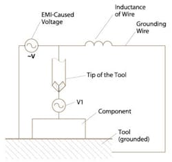
For example, Figure 2 shows a typical automated process where an actuator, in this case an electric screwdriver, fastens a screw to a device during assembly. EMI-caused voltage is generated when a stepper motor operates, which is typical for many such tools. Because of inductance in the ground wire, there is a voltage difference (V1) between the tip of the tool and a component. This voltage may reach significant amplitude.
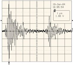
Consider the real-world example shown in Figure 3. In this case, the peak voltage reached almost 4 V. For many components, this voltage may pose no problem, but for some components such as magnetic heads and high-sensitivity semiconductors, it can cause irreversible damage or latch-up.
The mechanism of damage is different from ESD damage. Unlike ESD where a limited amount of charge dissipates very quickly, this high-frequency noise has characteristics of a voltage source with virtually unlimited current capability and long duration.
Can equipment have a good EMI ground and a poor real ground? Though it is theoretically possible to have a very quiet tool that would exhibit very low emissions levels even when it is not properly grounded, the probability is nearly zero. Any metal object would receive ambient electromagnetic radiation, plentiful and abounding in a typical production environment, and in turn, radiate it back if a good ground path is not present.
Is a static-dissipative ground enough for EMI? An example of such a ground is the metal chain connecting equipment to a static-dissipative floor. While sufficient for extremely slowly changing electrostatic voltages, for high-frequency signals, such a connection essentially represents an open circuit and is completely ineffective.
Measurement Methodology
Once the problem of grounding at high frequencies is recognized, diligent facility and equipment engineers would be concerned with the methodology of measuring ground quality at high frequencies and the ways to improve it.
The ideal ground is an infinite sink for all the energy conducted to it. It should have no voltage on it, DC or AC (including high frequencies). If any voltage is present, the ground quality is questionable. Measurements of DC or 50/60-Hz AC voltage on the ground are straightforward: just connect one probe of a multimeter to a reference ground point and the other probe to the equipment of interest.
The situation gets more interesting at high frequencies since the measurement instrumentation typically is expensive and complicated. There is a way, however, to measure the EMI quality of a ground using affordable and easy-to-use instruments.
If any voltage is present on an object, it will generate a corresponding electric field. Measurements of electrostatic voltage, for example, are based on measurements of electric fields emanating from the charged object. In a similar fashion, measurements of high-frequency voltages on the ground can be assessed with a high-frequency field-strength meter placed at a controlled distance from the object.
The field-strength meter does not provide precision measurements of high-frequency signals. It does give repeatable reference values that are proportional to the voltages on the conductive surfaces. A portable, sensitive, broadband electromagnetic field-strength meter with a directional antenna and the capability to measure peak values of transient signals is ideal for these measurements.
EMI measurements only are valid on conductors such as wires or metal equipment enclosures, not on insulators or static-dissipative materials.
A consideration must be given for accurate ground connectivity measurements in the presence of noise. A conventional multimeter determines ground resistance by applying some current to the load and measuring the load voltage. This works well unless there is extraneous noise when the tools are operational. In these situations, the multimeter may show a very significant error or odd readings such as negative resistance.
The difference in ground-resistance measurements on the same tool often results between operational idle states. The proper way of measuring ground connectivity is not as DC resistance but as AC impedance as specified by ANSI 6.1, ANSI/ESDA S.20.20, and other standards. A conventional multimeter does not comply with the standards requirements.
Also, an AC impedance meter can be affected by high-frequency noise. For accurate measurements of ground, it is better to use an instrument that can separate measurement signal and noise.
EMI Audit
An EMI audit is essential to determine EMI grounding problems. Initial measurements of EMI on the ground of each tool will give you a good baseline of the status of the ground at your facility. It also will provide you with information on EMI hot spots. There are some basic, common-sense rules for such an audit:
• Use consistent methodology. Specifically, measure emissions at the same distance from the grounding surface, preferably at ” in all locations.
• Pay attention to background electromagnetic emissions. If the background is noisy, it may affect the readings. Record relative emissions readings in the area away from the ground as well.
• Measure emissions when the equipment is operating.
• Measure both continuous and peak emissions values.
• Overlay the EMI levels on the floor plan to help identify hot spots.
Case History
An EMI audit was performed on the ground in a semiconductor fab at Texas Instruments in Dallas. All ground wires in the facility were connected to the copper grounding plates in the underfab. In some cases, there were high concentrations of wires connected to a single grounding plate.
Data was collected on various pieces of equipment in the fab and on each ground plate using an EM Eye Field-Strength Meter. The floor plan of collected data is shown in Figures 4a and 4b. The highest EMI points in the fab have good correlation with the quality of ground on copper plates in the underfab.
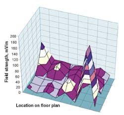
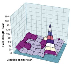
During the same EMI audit, it was discovered that several tools weren t grounded at all. High emissions levels revealed these problems. Such data provides a good baseline and clear guidelines on where to improve the quality of the EMI ground.
How to Make a Good EMI Ground
In most cases, it costs just about the same to make a good ground as a poor one. Here are some of the basics.
Safety First
Under no circumstances should you compromise safety. Always provide a good connection of your equipment to ground in accordance with safety regulations.
Known-Good Ground
A ground junction that already is noisy is no help in reducing EMI. Make sure your main point of connection to the ground is quiet.
Length of Ground Wires
Do not use long and coiled ground wires. Trim ground wires to the required length.
Braided Cables
The lower the impedance of ground wires, the less EMI on the ground. Due to the skin effect at high frequencies, solid wires have fairly high impedance at high frequencies. The best solution is to use wide, braided cables. The more noise equipment produces, the wider the cable should be.
No Ground Chain
To prevent EMI from propagating from one tool to another via a serial ground connection, use a star configuration whenever possible.
Ground Connections
Distribute the ground connections. Do not concentrate the ground connection of many tools at one point.
Emissions Violators
Very noisy equipment should be connected to the ground separately so EMI will not spread to other equipment.
Continuous Monitoring
In an environment where tools often are repaired, maintained, or moved, the possibility of disconnecting the ground or making it less acceptable is a common occurrence. Continuous monitoring alerts personnel to the problem and provides a record of the status of the ground for troubleshooting should a mysterious failure occur.
Efforts to improve the ground will pay off in reducing downtime and increasing tool availability, decreasing product defects and loss caused by equipment malfunction.
About the Authors
Vladimir Kraz is president of Credence Technologies. Prior to founding Credence Technologies, he worked on CDMA, GSM, WLAN, satellite, and other wireless and wired data and voice communications and industrial controls. Mr. Kraz has M.S.E.E. and M.S.M.E. degrees from universities in Russia and is a member of IEEE, the ESD Association, and AES. e-mail: [email protected]
J. E. Patrick Gagnon is the metrology equipment engineer in the KFAB at Texas Instruments. Previously, he was employed by Motorola, SVGL, Xerox, and Eastman Kodak. Mr. Gagnon holds a bachelor's degree from McGill University of Montreal. e-mail: [email protected]
About the Author
Comment About the Article
To join the conversation, and become an exclusive member of Electronic Design, create an account today!

Leaders relevant to this article: