An amplifier is used to increase the power level of the input signal for many reasons. George Bollendorf, marketing and business development manager at EMPOWER RF Systems, discussed a few. He said, “The need for higher power levels is driven by several factors including the trend in EMC compliance requirements for testing at higher field strengths spurred by the electrification of vehicles and more generally the increasing proliferation of RF and microwave energy in our environment. Additionally, longer test distances arising from the desire to radiate entire vehicles and systems are also an important factor adding to the need for more RF amplifier power. Automotive HIRF 600 V/m is a good example as well as the recent extension of the IEC specification to test more products to 6 GHz at higher field strengths.”
Courtesy of Vectawave Technology
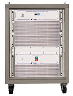
As test requirements change, so too do amplifier designs. Dan Eckersley, project engineer at Vectawave Technology, said the company had used the latest-generation LDMOS devices in the 500-W Model VBA 2700/3100-500 class AB amplifier. When used with a suitable antenna and chamber, it is capable of delivering a 600-V/m field, primarily required during 2.7-GHz to 3.1-GHz S-band automotive radar pulse EMC testing. Similar technology is used in the 1-kW Model VBA 1200/1400-1000, which operates in the 1.2-GHz to 1.4-GHz L band (Figure 1).
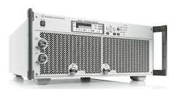
In addition to LDMOS, new EMC amplifiers also are taking advantage of the latest GaN devices to achieve both higher bandwidth and power. According to Dr. Wolfram Titze, director of product management transmitter and amplifier systems at Rohde & Schwarz, “For EMC applications, class A typically is used due to the linearity and robustness requirements.” He explained that because class A amplifiers are the least efficient of the classes, cooling is key to achieving a compact and lightweight design. As an example of what’s possible, a 500-W R&S amplifier operating from 80 MHz to 1 GHz is available in the Model BBA150-BC500 4U-high desktop unit (Figure 2).
Courtesy of Rohde & Schwarz
Linearity
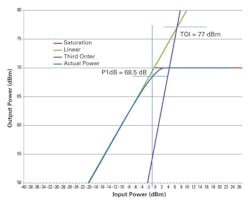
At a sufficiently large input level, an amplifier’s output will have dropped by 1 dB below the amplitude it would have had were the amplifier perfectly linear. This is the P1dB point and generally considered to be the highest power level that still provides a reasonably linear output signal. The output has become compressed by 1 dB.
As shown in Figure 3, based on the AR RF/Microwave Instrumentation Model 10,000A225A-A, the P1dB point for this 10-kW LDMOS amplifier occurs at a -0.5-dBm input level with the gain set to the 70-dB maximum. The output power at the P1dB point is 7,000 W, corresponding to 68.5 dBm. The actual power curve intersects the P1dB point at this value but the figure is only approximate between there and the 70-dBm saturation level.
Source: AR RF/Microwave Instrumentation
Many manufacturers specify amplifiers in the same way as AR—they quote maximum gain and the P1dB point. In contrast, R&S equates the two values on the assumption that if the amplifier is going to be used for EMC testing, then it will be operated at its P1dB point, and that’s the highest power level of interest to the test engineer.
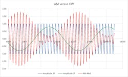
An 80% AM modulated signal often is used in EMC testing. The peak envelope power (PEP)—the power level when the modulation is at its maximum—is 5.09 dB above the CW power, and the average power with 80% modulation is 1.2 dB higher than the CW power. These higher levels will determine the amplifier power you need.
Reference 1 includes an example of a 50-W CW signal with 80% AM modulation, as shown in Figure 4. For this example, PEP = 161.5 W (50 W + 5.09 dB), and average power = 66 W (50 W + 1.2 dB). Although the CW power is only 50 W, an amplifier with P1dB = 160 W is needed to ensure that the modulation peaks are not compressed.
Courtesy of ETS-Lindgren
A common definition of amplifier linearity assumes that only the fundamental and third harmonic terms of a power series are needed.2 This is approximately true for solid-state amplifiers. Starting with the transfer function in equation 1, and substituting a trigonometric identity for cos,3 a couple of relationships can be derived:
TOI is a power level indicated by the V2 in equation 2. For small amounts of third-order distortion—small D3—TOI will be larger than the amplifier’s saturated output power so it is only a theoretical point; it can never actually be reached by the amplifier.
From the equations, you also can show that TOI occurs at a power level about 9.5 dB higher than the P1dB point. For the AR amplifier, the difference is 8.5 dB, indicating that the output isn’t exactly described by equation 1. Nevertheless, TOI is a good indication of linearity: the higher, the better.
Some amplifier datasheets also list a P3dB point. For an amplifier with its P1dB point only slightly below the maximum saturated output level, the P3dB point is very close to saturation. This isn’t the case for many higher-distortion traveling wave tube amplifiers that may have the P1dB point as much as 6 dB below saturation.
Efficiency
High-power amplifiers typically consist of several lower power assemblies and a means to combine the power output from each. Vectawave’s Eckersley said the combiner in some of his company’s amplifiers was based on a stripline design that used high thermal conductivity circuit board materials.
EMPOWER’s Bollendorf explained, “Efficiency gains come from patented technology replacing lossy internal RF cables and connectors with PCB technology connecting the driver, splitter, RF palettes, and combiner. Efficiency gains above 1 GHz come from an in-house custom-designed combiner with proprietary coating techniques. This patented architecture results in typical loss savings of 0.5 dB, which amounts to over 100 watts on a 1-kW system.”
Dr. Titze from R&S said, “To achieve very high power levels, several [high-power amplifiers] are combined with dedicated RF combiners. The required design parameters for a combiner such as good input matching, broad bandwidth, low losses, and decoupled inputs are contradicting requirements due to fundamental laws of physics. If we talk about broadband amplifiers that operate over several octaves, broadband bridge networks and cascaded Wilkinson combiners are candidates to fulfill this job. For very high power combiners, for example, in the kW range, a low loss coaxial system is the preferred architecture.”
Cap Wireless, now part of TriQuint Semiconductor, developed the Spatium amplifier that uses spatial power combining to sum the outputs from several radially oriented MMIC amplifiers. The advantages of the technique include providing relatively high power in a small package as well as broadband operation. In this approach, the output fields are directly combined. A CAP Wireless paper on the TriQuint website describes the Spatium structure as “an antipodal finline antenna array.”3
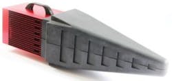
Taking a planar approach to field combining, ETS Lindgren’s EMField Generator adds the fields generated by three parallel flat antennas, eliminating an EMC test engineer’s usual worries about “… amplifier power levels, 1-dB compression points, cable losses, and illumination areas.”1 Four models address combinations of the 1-GHz to 3-GHz or 1-GHz to 6-GHz frequency ranges and 1-m or 10-m test distances (Figure 5).
Courtesy of ETS-Lindgren
At high power levels, even coaxial connectors can be a problem. Dr. Titze added, “You also have to take into account that the output power of a high-power amplifier system often reaches the limits of the specifications of the available RF connectors because connectors with a high power handling capability are frequency limited due to their mechanical dimensions. These limits can especially be reached under continuous operation together with bad VSWR conditions. Rohde & Schwarz takes particular care that the connector chosen can handle both the thermal stress and the high voltage that may occur at the connector for continuous operation, even under bad VSWR conditions.”
AR also uses proprietary combiner techniques. In addition, the company’s Joe Diesso, corporate vice president of marketing, explained that, “… gains also are attributed to a number of other factors, such as the use of either die or packaged transistors, design, simulation tools, and manufacturing techniques.”
A further factor used by EMPOWER is digitally controlled bias currents to achieve the best balance of linearity, power, and efficiency. The company’s Bollendorf said that this was a design strategy that remains a capability in EMPOWER’s manufactured amplifiers, with the added benefit that the company can remotely configure IDD and VDD for efficiency and linearity trade-offs if a customer’s requirements change.
Output protection and VSWR
Reflections are caused by impedance mismatches, which commonly occur in EMC testing:
For Γ = 0.7143, VSWR = 6, and the amount of reflected power is 50%. In a class A amplifier, the theoretical efficiency is only 50% with actual efficiency in the 20% to 30% range, so output devices tend to be large and robust. When operated well within their safe operating areas (SOA), there is sufficient margin that high amounts of reflected power can be absorbed.
Returning to the 50-W example from reference 1, because the average power that the 160-W amplifier’s output stage provides is only 66 W (50 W + 1.2 dB), a large amount of reflected power can be accommodated. In the example, a VSWR of 6 is assumed, giving 50% reflection—so an additional 33 W is dissipated in the output stages.
Class AB amplifiers can have actual efficiencies around 60%. This seems to be a big advantage, and it can be. With higher efficiency, it’s possible to use smaller devices and less heatsinking, a perfectly adequate combination for CW operation. However, with high VSWR values, the devices may be driven outside of their SOA. To avoid this, according to reference 1, “… class AB amplifiers are fitted with a VSWR protection system that lowers the drive to the final stage and reduces the average power that must be dissipated.”
As an example of a typical amplifier rating, AR’s 10,000A225A-A datasheet quotes mismatch tolerance as “100% rated power without foldback up to 6.0:1 mismatch,” above which reflected power may be limited to 5,000 W. Further, the amplifier is limited to 3,000 W reflected power from 100 MHz to 225 MHz. The company’s Diesso added, “To ensure performance of the amplifiers, each amplifier is tested to [withstand] … severe mismatches prior to customer delivery. The ability to continue operation when subjected to mismatches as extreme as opens and shorts is a significant advantage.”
Vectawave’s Eckersley discussed output protection for the company’s amplifiers. He said, “In the case of the narrowband, Class AB [500-W S-band and 1-kW L-band] amplifiers …, it is straightforward to provide protection against output mismatches. Microwave circulators can, over a narrow frequency range, direct reflected power to a separate, matched load and are fitted to these amplifiers. The overwhelming majority of Vectawave’s amplifiers operate in Class A. The device currents are regulated and fixed and will remain so under any level of reflected power, producing no additional thermal stress on the devices under severe mismatch conditions.”
All R&S amplifiers, according to Dr. Titze, are designed “… to operate on a VSWR >6 at full output power without any damage in a 24/7 mode. For higher VSWR, they may fold back dependent on the mismatch but will always deliver at least half their nominal output power, even under short or open conditions…. This kind of behavior can be achieved by monitoring closely the main parameters of the transistors in the amplifier and the forward and reflected power at the output.”
Finally, EMPOWER’s Bollendorf explained what he termed smart protection. He said that the protection method in his company’s amplifiers varies, “depending on the input signal modulation to maximize output power for that modulation scheme. For example, multitone inputs, AM, FM, pulse, digital modulation—all have different methods of self-protection that are based on real-time digital filtering and digital signal processing algorithms that are implemented in our input and output peak detector design.” Measurements internal to the company’s Next Gen amplifiers, such as the 1-kW Model BBS3K4AUT, provide automatic gain control that can significantly reduce test time.
Summary
Among the many factors influencing the selection of EMC amplifiers, the P1dB power rating and high VSWR tolerance are near the top of the list. Size and weight also can be important factors, as Bollendorf commented. “High power density is an advantage in airborne and land mobile electronic warfare, radar, and communications.” He concluded, “In the compliance lab environment, the ability to move a kilowatt amplifier around the facility on a cart is an advantage if not a necessity, and being able to power it with single-phase 208 V is very convenient and reduces the power bill.”
References
- EMField Generator, ETS-Lindgren, Application Note 14.001, October 2014.
- Lecklider, T., “Classy Amplifiers Simplify EMC Test,” EE-Evaluation Engineering, February 2009, pp. 38-45.
- Courtney, P. G., et al, “High Efficiency 80W X-Band Power Amplifier using Coaxial Waveguide Spatial Power Combining Technique,” CAP Wireless, November 2009.
For more information
