Elastomeric Actuators Lift Aerial Micro-Robot
What you’ll learn:
- Why and how the flexible actuators were fabricated.
- How they were used in an aerial micro-robot.
- The performance obtained with these actuators.
While the electronics for drones and aerial robots of all sizes continue to shrink at an impressive pace, achieving the same for micro-actuators has been a challenge, as the laws of physics in general and mechanical functions specially push back against those attempts. That hasn’t stopped innovative researchers from conceiving and executing new approaches or extending older ones, though.
As evidence of this ongoing effort, MIT researchers have demonstrated tiny drones with soft, very durable actuator muscles. Existing dielectric elastomer actuators (DEAs) require higher driving voltages, and their power density and lifetime remain substantially lower as compared to existing piezoelectric bimorphs and electromagnetic motors. However, the new MIT design can operate with a voltage that’s 75% lower than those versions while carrying 80% more payload.
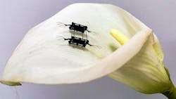
The rectangular micro-robot has four sets of wings comprised of two joined pairs. Each wing is driven by a soft actuator that’s like an artificial muscle, which rapidly flaps the robot’s wings (Figs. 1 and 2). These muscle-like actuators consist of layers of elastomer that are sandwiched between two very thin electrodes and then rolled into a squishy cylinder. When voltage is applied to the actuator, the electrodes squeeze the elastomer, and that mechanical strain is used to flap the wing.
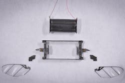
1. The pieces of the aerial micro-robot before assembly; note the two flexible actuators which are also the wings.
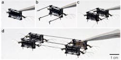
2. Assembly of the four-module robot: (a) A single flapping-wing robot module. (b) Four carbon-fiber connection bars are attached to the robot airframe. (c) A second robot module is attached to the connection bars, creating a two-module robot. (d) Two two-module robots are attached using three carbon-fiber connection bars.
The more surface area the actuator has, the less voltage is required. To achieve that goal, the team built the artificial muscles by alternating between as many ultra-thin layers of elastomer and electrode as possible. However, as the elastomer layers get thinner, they become more mechanically unstable.
When operated at 400 Hz, the 143-milligram DEA generates a force of 0.36 newtons and displacement of 1.15 mm. This DEA is incorporated into an aerial robot to demonstrate the resultant high performance.
The robot achieves a high lift-to-weight ratio of 3.7, low hovering voltage of 500 V, and a long lifetime exceeding 2 million actuation cycles. This isn’t random lift or flight, as the robot demonstrated the longest and best-performing flight among existing sub-gram aerial robots, with 20 seconds of hovering time, and position and attitude error smaller than 2.5 cm and 2 degrees.
“People tend to think that soft robots are not as capable as rigid robots.” said project leader Prof. Kevin Chen, in the Department of Electrical Engineering and Computer Science, the head of the Soft and Micro Robotics Laboratory in the Research Laboratory of Electronics (RLE). “We demonstrate that this robot, weighing less than a gram, flies for the longest time with the smallest error during a hovering flight. The take-home message is that soft robots can exceed the performance of rigid robots.”
Meeting the Fabrication Challenge
A flex-wing concept isn’t enough; it must be built and tested. The researchers were able to create an actuator with 20 layers, each of which is 10 µm in thickness (Fig. 3)—a first-time accomplishment. To do this, they had to reinvent parts of the fabrication process.
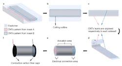
3. Illustrations of DEA assembly: (a) Depiction of the elastomer-electrode multi-layer. The patterns of odd and even numbered CNT electrodes are offset. (b) Outline of the DEA release cut. (c) The DEA’s top and bottom edges correspond to the two exposed electrodes. (d) The DEA is rolled into a cylindrical shell. (e) The two ends of the DEA are exposed for making electrical connections. (f) Conductive epoxy and carbon-fiber endcaps are applied on each end to make electrical connections.
For example, during spin coating, an elastomer is poured onto a flat surface and rapidly rotated, and the centrifugal force pulls the film outward to make it thinner. “In this process, air comes back into the elastomer and creates a lot of microscopic air bubbles. The diameter of these air bubbles is barely 1 micrometer, so previously we just sort of ignored them,” explained Chen. “But when you get thinner and thinner layers, the effect of the air bubbles becomes stronger and stronger. That is traditionally why people haven’t been able to make these very thin layers.”
The researchers found that if they perform a vacuuming process immediately after spin coating, while the elastomer was still wet, it removes the air bubbles. Then they bake the elastomer to dry it. Removing these defects increases the power output of the actuator by more than 300% and significantly improves its lifespan, said Chen.
The researchers also needed to optimize the thin electrodes, which are composed of carbon nanotubes (CNTs). The challenge is that higher concentrations of CNTs increase the actuator’s power output and reduce voltage, but dense layers also contain more defects. The carbon nanotubes have sharp ends that can pierce the elastomer, which causes the device to short out. After much trial and error, the researchers found the optimal concentration.
A third problem comes from the curing stage. As more layers are added, the actuator takes longer and longer to dry. “The first time I asked my student to make a multilayer actuator, once he got to 12 layers, he had to wait two days for it to cure,” said Chen. “That is totally not sustainable, especially if you want to scale up to more layers.”
They found that baking each layer for a few minutes immediately after the CNTs are transferred to the elastomer cuts down the curing time as more layers are added.
Modeling, Test, Evaluation
This MIT group has extensive experience with aerial micro-robots, so they began with a very basic electrical model (Fig. 4) and then extended it to far more complex versions. They evaluated the performance across various parameter pairings including (but not limited to) basic force measurements (Fig. 5).
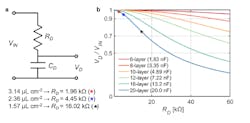
4. DEA electrical model: (a) Circuit model of DEA with the modeling parameters. VIN is the input voltage, and VD is the voltage drop across the capacitance. RD and CD are the resistance and the capacitance of the DEA, respectively. Resistance values of the DEAs made of the filters with different CNT concentrations also are presented. (b) Estimation of the voltage drop on the capacitance along varying resistance when an ac input with 400 Hz is applied to the 6-, 8-, 10-, 12-, 16-, and 20-layer DEAs. Markers represent the estimated VD/VIN ratio of the 20-layer DEAs of different CNT concentrations.
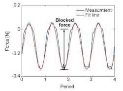
5. Shown is the DEA blocked-force measurement. The blue curve shows the sensor measurement when the DEA is driven by a 400-Hz sinusoidal voltage input; the orange curve shows the fitted line. As indicated by the black arrows, the blocked force is calculated as the zero to peak value.
The work is detailed in a paper published in Advanced Materials, “High Lift Micro-Aerial-Robot Powered by Low Voltage and Long Endurance Dielectric Elastomer Actuators.” In addition, their 25-page “Supporting Information” posting contains detailed models; in-depth aerodynamic, electrical, and mechanical analyses; and a full suite of test results. Given the nature of the project, it’s not surprising that there are also several short videos are available, as well as this interesting two-minute overview video for the general public:
About the Author

Bill Schweber
Contributing Editor
Bill Schweber is an electronics engineer who has written three textbooks on electronic communications systems, as well as hundreds of technical articles, opinion columns, and product features. In past roles, he worked as a technical website manager for multiple topic-specific sites for EE Times, as well as both the Executive Editor and Analog Editor at EDN.
At Analog Devices Inc., Bill was in marketing communications (public relations). As a result, he has been on both sides of the technical PR function, presenting company products, stories, and messages to the media and also as the recipient of these.
Prior to the MarCom role at Analog, Bill was associate editor of their respected technical journal and worked in their product marketing and applications engineering groups. Before those roles, he was at Instron Corp., doing hands-on analog- and power-circuit design and systems integration for materials-testing machine controls.
Bill has an MSEE (Univ. of Mass) and BSEE (Columbia Univ.), is a Registered Professional Engineer, and holds an Advanced Class amateur radio license. He has also planned, written, and presented online courses on a variety of engineering topics, including MOSFET basics, ADC selection, and driving LEDs.
Comment About the Article
To join the conversation, and become an exclusive member of Electronic Design, create an account today!

Leaders relevant to this article: