Fast-Slewing and Settling Buffer Amplifier IC Reaches 3 GHz
“Buffer” is one of the many words in electronic and computer engineering with multiple meanings. It can refer to a distinct physical memory dedicated to temporary data storage, or it can be a software-defined memory allocation for in-process data. Buffer also may refer to a hardware driver for a low-impedance load such as a relay or LED.
However, in classical analog signal-chain circuitry, it refers to a component residing between two stages to assure that the signal source is compatible with the characteristics of its load stage. An RF buffer amplifier usually doesn’t perform traditional signal “processing” tasks such as providing filtering or noise rejection. Instead, its usual role is to ensure a fit between source and load while insulating the source’s output from the characteristics and variations of the load’s input.
This may require the buffer to transform the source’s high-impedance output, so that it’s “comfortable” driving the low impedance of the load. The right buffer amplifier can make the difference between realizing “pretty good” versus “really, truly good” system performance.
TI’s Very-Wide-Bandwidth Buffer Amp
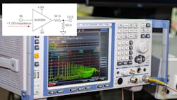
To address these requirements, the BUF802 buffer amplifier from Texas Instruments features large-signal bandwidth up to 3.1 GHz at 1-V p-p input (and as high as 2 GHz at 2 V p-p) with a fast slew rate (7000 V/µs) and fast settling time (0.7 ns to 1%) (Fig. 1).
Claimed to be the widest-bandwidth high-input-impedance buffer amplifier of its type on the market, target applications include high-performance and precision test-and-measurement designs, including oscilloscopes, active probes, and wideband data-acquisition systems.
TI also maintains that the bandwidth offered by the BUF802 was previously attainable only via application-specific integrated circuits (ASICs). ASICs, though, inherently required a significant commitment in design time, complexity, risk, and cost due to the need for dozens of discrete components such as FETs, bipolar transistors, and protection diodes.
Input voltage noise is just 2.3 nV/√Hz, while input impedance—another critical parameter in these applications—is 50 GΩ in parallel with 2.4 pF. Operating from a ±4.5- to ±6.5-V supply, the JFET-input BUF802 can easily drive the ubiquitous 50-Ω load. It also offers user-adjustable quiescent current for power/performance tradeoff and an integrated input/output clamp with fast overdrive recovery, which is another concern in these applications.
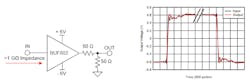
The BUF802 has been designed to operate in two modes—Buffer (BF) Mode and Composite Loop (CL) Mode—using its parallel Main Path and Auxiliary Path (Fig. 2).

In applications where extreme dc precision isn’t as critical with offsets under 100 mV, or where the input is ac-coupled, the BUF802 can be employed as a standalone input buffer where only its Main Path is used. In this mode, the BUF802 uses the JFET, output driver, and bipolar transistors in the Main Path to reproduce the signal applied to the input IN at its output OUT.
Even More Precision
If higher precision than offered by the BUF802 alone is required, designers can configure the BUF802 in CL Mode in conjunction with a separate precision amplifier. In this mode, the BUF802 uses the Auxiliary Path and the Main Path to control the output voltage, and simultaneously provide high dc precision and 3-GHz bandwidth with 1 μV/°C maximum offset drift.
In this scenario, the composite loop splits the applied signal into low-frequency and high-frequency components and passes them over to different circuits with suitable transfer function. The low- and high-frequency signal components are then recombined within the BUF802 and reproduced at the OUT pin. (No, it’s not the Doherty amplifier topology, as the BUF802 mode is pre-selected by the user and not determined by the signal magnitude.)
In addition to the comprehensive 37-page BUF802 datasheet with specifications, tables, graphs, considerable and very necessary applications information, and demonstration PCB layout details, TI also has an informative blog post “Simplify analog front-ends with Hi-Z buffers.”
Further, the company offers the BUF802RGTEVM evaluation module (EVM), very useful for buffer amplifiers such as this where layout is critical (Fig. 3). This EVM can be configured for composite loop mode with a precision amplifier or just the BUF802 device alone. It features single or split supplies and footprints for SMA connectors on all analog inputs and outputs. The EVM layout is optimized to reduce parasitic coupling and provide the best signal fidelity across the frequency spectrum.
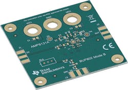
The BUF802 comes in a 3- × 3-mm, 16-pin, very thin no-lead (VQFN) package and is priced at $1.80 in 1,000-unit quantities. The BUF802RGTEVM evaluation module costs $25.
About the Author

Bill Schweber
Contributing Editor
Bill Schweber is an electronics engineer who has written three textbooks on electronic communications systems, as well as hundreds of technical articles, opinion columns, and product features. In past roles, he worked as a technical website manager for multiple topic-specific sites for EE Times, as well as both the Executive Editor and Analog Editor at EDN.
At Analog Devices Inc., Bill was in marketing communications (public relations). As a result, he has been on both sides of the technical PR function, presenting company products, stories, and messages to the media and also as the recipient of these.
Prior to the MarCom role at Analog, Bill was associate editor of their respected technical journal and worked in their product marketing and applications engineering groups. Before those roles, he was at Instron Corp., doing hands-on analog- and power-circuit design and systems integration for materials-testing machine controls.
Bill has an MSEE (Univ. of Mass) and BSEE (Columbia Univ.), is a Registered Professional Engineer, and holds an Advanced Class amateur radio license. He has also planned, written, and presented online courses on a variety of engineering topics, including MOSFET basics, ADC selection, and driving LEDs.
Comment About the Article
To join the conversation, and become an exclusive member of Electronic Design, create an account today!

Leaders relevant to this article: