Members can download this article in PDF format.
What you’ll learn:
- The very basics of operational amplifiers.
- Learn comparator, inverting, and non-inverting op-amp configurations.
An operational amplifier, or op amp, is a dc-coupled high-gain electronic voltage amplifier with differential inputs and a single-ended output. In essence, it boosts weak dc signals with an output potential that can be 100,000X larger than the potential difference between input terminals.
Op amps have been around since the early 1940s, existing alongside vacuum-tube circuitry, and became commercially available in the 1950s, with their solid-state cousins entering the market a decade later. They’re an essential part of any analog signal chain, often working as a crucial part of the interface between sensors and devices such as analog-to-digital converters (ADCs).
Op amps are praised for their versatility and can be found in many electronic devices, including scientific, consumer, and industrial platforms. With only a handful of external components, they can be made to perform a wide variety of analog signal-processing tasks, including conditioning and filtering. They’re also affordable, with most amplifiers selling for under a dollar and often less when bought in bulk.
Op-Amp Functionality
Op amps are voltage-amplifying devices designed to be used with external feedback components—resistors and capacitors—that are situated between their output and input terminals. The feedback components determine the resulting function or "operation" of the amplifier. Depending on the different feedback configurations (resistive, capacitive, or both), the amplifier can perform a variety of operations, thus earning the name "operational amplifier."
Op amps are essentially three-terminal devices outfitted with a pair of high impedance inputs, one acting as an inverting input and the other as non-inverted. They also feature two dc power leads (positive and negative) and an output terminal, which can sink and source either a voltage or a current.
In a linear op amp, the output signal is the amplification factor, known as the amplifier's gain multiplied by the value of the input signal. Depending on the nature of these input and output signals, there can be four different classifications of op-amp gain.
Those pair of dc power-supply inputs usually determine the voltage limits of the outputs. They may also connect to positive voltage and ground, like those found in circuits, or connect to positive and negative power supplies. One way to achieve this is by connecting a voltage divider (made of resistors) between a single power supply and an op amp.
With that said, an op amp's operation is simple: The voltages at the inputs are compared, determining whether the output moves toward the positive supply voltage or the negative.
To better understand, imagine an op amp connected to a 9-V power supply with the two inputs labeled non-inverted (positive) and inverted (negative). If the voltage at the positive input is larger, the output will gravitate toward the positive supply voltage (9 V). If the voltage at the negative input is higher, the output will move to the negative supply voltage or ground.
When the output reaches either of those points, it produces "saturation," where the signal is at the maximum rated gain. This is described as the ratio or multiplier between the signal at the inputs vs. the signal at the output.
Basic Op-Amp Circuits
Comparator circuit
A comparator circuit (Fig. 1) compares two input voltages and outputs a binary signal indicating which is larger. If the non-inverting (+) input is greater than the inverting (−) input, the output goes high. If the inverting input is greater than the non-inverting, the output goes low.
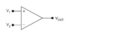
Comparators are often used to check whether an input has reached a predetermined value. In most cases, a comparator is implemented with a dedicated comparator IC, but op amps may be utilized as an alternative. A simple comparator can be created using an op amp without negative feedback. The high voltage gain enables it to resolve minimal differences in the input voltage.
Inverting circuit
There are several different op-amp circuits, each functioning differently depending on the variables for the inputs. Because the op amp's gain is so high, even minor differences in the inputs will rapidly drive the output voltage to its maximum or minimum value. As a result, op amps are usually connected to a negative feedback, which is evident in an op-amp inverting circuit (Fig. 2). An inverting op amp features an output voltage that changes in the opposite direction as the input voltage.
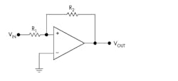
The inverting input refers to the pin configuration. In this case, the inverting input is the terminal marked with a minus sign (−), and the non-inverting input is marked with a plus sign (+). These also can be referred to as negative and positive terminals. If the output isn’t connected to a power voltage, then the voltages applied to the inverting (−) and non-inverting (+) inputs are equal.
To get a better understanding, we need to follow two rules—the current rule, where no current flows into the op amp's inputs (I+ = I− = 0), and the voltage rule, where the output of the op amp attempts to ensure that the voltage difference between the two inputs is zero (V+ = V−).
The current flowing through R1 is I = VIN/R1, and since the current rule states that the inputs draw no current, all of that current must then flow through R2. Because the inverting input is at virtual ground, the output of the inverting op amp is VOUT = −IR2 = −VINR2/R1. Thus, the gain of the inverting op-amp circuit is −R2/R1. The gain is negative, meaning the output is out of phase with the input.
Non-inverting circuit
A non-inverting op amp (Fig. 3) has an output voltage in phase with the input voltage. This type of amplifier produces an output signal in phase with the input signal, unlike the inverting amplifier's output, which is out of phase. Both inverting and non-inverting op amps can be constructed from one op amp and two resistors, just in different configurations.
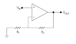
Using the two rules mentioned earlier, the current going through R1 can then be given as VIN/R1, while the inputs draw no current. Therefore, all current flows through R2. The output voltage then can be given as VOUT = VIN + (VIN/R1)R2, while the gain is then VOUT/VIN = 1 + (R2/R1). Because the gain will never be less than 1, the non-inverting op amp will produce an amplified signal in phase with the input.
Op-Amp Applications
Operational amplifiers can be utilized in a wide range of applications. By adding more resistors or capacitors to the circuit, they can be applied to create many different computational circuits.
For example, an adder/summing circuit may combine multiple input voltages to a single output voltage. These circuits can help build devices like audio mixers and digital-to-analog converters (DACs). Replacing a feedback resistor with a capacitor, op amps can be used to create an integrator, which produces an output voltage that's proportional to both the amplitude and the duration of the input signal.
Op amps also function as signal filters and noise-reduction devices in electronics tailored for telecommunications, audio systems and power supplies. In addition, they can be used as 555 timers by creating an astable multivibrator, which connects a resistor and capacitor to the inverter input and a voltage divider at the non-inverted input. Of course, op amps are ideal for voltage followers, current-to-voltage converters (CVCs), active rectifiers, and more.
About the Author

Cabe Atwell
Technology Editor, Electronic Design
Cabe is a Technology Editor for Electronic Design.
Engineer, Machinist, Cartoonist, Maker, Writer. A graduate Electrical Engineer actively plying his expertise in the industry and at his company, Gunhead. When not designing/building, he creates a steady torrent of projects and content in the media world. Many of his projects and articles are online at element14 & SolidSmack, industry-focused work at EETimes & EDN, and offbeat articles at Make Magazine. Currently, you can find him hosting webinars and contributing to Electronic Design and Machine Design.
Cabe is an electrical engineer, design consultant and author with 25 years’ experience. His most recent book is “Essential 555 IC: Design, Configure, and Create Clever Circuits”
Cabe writes the Engineering Life & Engineering on Friday blog on Electronic Design.
See Cabe's cartoons & comic strips here.
Comment About the Article
To join the conversation, and become an exclusive member of Electronic Design, create an account today!

Leaders relevant to this article: