Nanoflyer Uses Embedded EL Flashers for Tracking, Signaling

What you’ll learn:
- Why electroluminescence lighting makes sense for these microscale flyers.
- How EL emitters were fabricated to meet the multiple challenges and constraints.
- The tracking performance the team achieved with an iPhone-based tracker compared to a commercial image-capture motion-tracking system.
There’s been a significant effort and demonstrable progress in building tiny, insect-like flying robots (often called microscale or nanoscale flyers), but they all have one problem: They are hard to visually track. Furthermore, it’s challenging to embed a communications link for them, as Bluetooth and other wireless protocols require additional circuitry and consume precious power.
These robots are often so lightweight that they can’t carry many sensors or RF transceivers. As a result, researchers must track them using bulky infrared cameras that don’t work well outdoors.
Lighting the Way
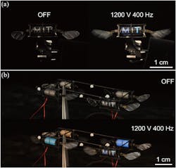
Now, a team at MIT has devised a way to implement an ancient signaling concept—the use of light and flashes—in these flying nanobots, using electroluminescence (EL) rather than relatively power-hungry and heavy LEDs and their support circuitry (obviously, “relatively” is the key word here). Inspired by fireflies, researchers created insect-scale robots that can emit light when they fly, which enables motion tracking and communication (Fig. 1).
The ability to emit light also brings these microscale robots, which weigh barely more than a paper clip, one step closer to flying on their own outside the lab. The researchers have shown that they can track the robots precisely using the light emitted by the robots and just three standard smartphone cameras. Use of EL could enable the robots to communicate with each other as well, in a coordinated project or have one signal another as to what needs to be done.
Previously, this team had devised a technique to build soft actuators (artificial muscles) called dielectric elastomer actuators (DEAs) that flap the wings of the robot. These durable actuators are made by alternating ultra-thin layers of elastomer and carbon nanotube electrodes in a stack and then rolling it into a squishy cylinder.
When a voltage is applied to that cylinder, the electrodes squeeze the elastomer, and the mechanical strain flaps the wing. During robot flight, a strong (>40 V/μm), high-frequency (400 Hz) electric field is generated within the DEA, exciting the EL particles to emit light.
Implementing the EL approach was accomplished by embedding minuscule electroluminescent particles into the artificial muscles. The EL scheme literally and figuratively builds the previous DEA developments by this same MIT Laboratory.
Glowing Actuators
To fabricate a glowing actuator, the team incorporated EL zinc-sulphate particles into the elastomer, but they had to overcome several challenges along the way. First, the researchers had to create an electrode that would not block light. They built it using highly transparent carbon nanotubes, which are only a few nanometers thick and enable light to pass through.
In existing EL displays, sensors, and robots, an elastomer-electrode layer is made for light emission, which adds substantial weight to the system. In addition, it requires a high-voltage and high-frequency driving signal that leads to high power consumption and low luminous efficacy (43 millilumens/W).
The team resolved this challenge by embedding EL particles in high-bandwidth DEAs that actuate at 400 Hz during the robot’s flight. Doing so enables simultaneous actuation and light emission using the same driving signal and doesn’t require additional robot components. Consequently, it only adds 2.4% of net robot weight and consumes an extra 3.2% of power at hovering flight conditions, judged to be an acceptable tradeoff.
“Traditionally, electroluminescent materials are very energetically costly, but in a sense, we get that electroluminescence for free because we just use the electric field at the frequency we need for flying. We don’t need new actuation, new wires, or anything. It only takes about 3% more energy to shine out light,” said Kevin Chen, who is Jr. Assistant Professor in the Department of Electrical Engineering and Computer Science (EECS), the head of the Soft and Micro Robotics Laboratory in the Research Laboratory of Electronics (RLE), and the senior author of the paper.
Adjusting the chemical combination of the zinc particles changes the light color. The researchers made green, orange, and blue particles for the actuators they built; each actuator shines one solid color.
As they prototyped the actuator, they found that adding the required zinc particles reduced its quality, causing it to break down more easily. To get around this, EECS graduate student and lead author Suhan Kim mixed the zinc particles into the top elastomer layer only. He made that layer a few micrometers thicker to accommodate for any reduction in output power (Fig. 2).
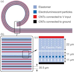
They also tweaked the fabrication process so that the actuators could emit multicolored and patterned light. The researchers placed a tiny mask over the top layer, added zinc particles, then cured the actuator. This process was repeated three times with different masks and colored particles to create a light pattern that spelled M-I-T.
Validation and Test
Once they fine-tuned the fabrication process, the mechanical properties of the actuators were tested, and a luminescence meter was used to measure the light intensity. That was followed by flight tests using a specially designed but very low-cost motion-tracking system—each electroluminescent actuator served as an active marker that could be tracked using iPhone cameras.
The cameras detect each light color, and a computer program they developed tracks the position and attitude of the robots to within a few millimeters of the result as determined by a state-of-the-art infrared motion-capture system.
They performed a sequence of closed-loop flights using a four-ELDEA-driven robot dubbed FireFly. In these flights, another commercial motion-capture system provided position and attitude tracking at 420 Hz. Based on previous work of this team, they implemented a custom flight controller running at 10 kHz in the MATLAB Simulink environment.
In addition, they demonstrated the ELDEAs can enable vision-based trajectory reconstruction using smartphone cameras that’s able to detect different colored light emitted from each ELDEA (Fig. 3). In turn, that can be used to calculate robot position and attitude.
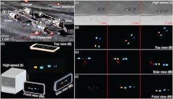
Compared to computer-vision strategies that detect passive robot features, this method requires less computation because each ELDEA represents a distinct active feature. (The image-capture phase required considerable up-front camera and system calibration.)
To film the robot flights, they used one high-speed camera and three smartphone cameras to capture five-second flights (Fig. 4). The three smartphone cameras were used to reconstruct the robot’s trajectory and attitude during flight, and this flight trajectory was analyzed. The root-mean-square (RMS) position and attitude errors are 2.55 mm and 2.60°, respectively, with a narrow error and uncertainty band.

In the future, they plan to enhance that motion-tracking system so it can track robots in real-time. The team is working to incorporate control signals so that the robots could turn their light on and off during flight and communicate more like real fireflies.
All aspects of the project are detailed in their readable eight-page paper “FireFly: An Insect-Scale Aerial Robot Powered by Electroluminescent Soft Artificial Muscles” published in IEEE Robotics and Automation Letters (I’m not sure how an eight-page paper qualifies as “Letters”). While that posted paper is behind a paywall, the MIT team has posted it here. Also, check out the one-minute YouTube video below showing assembly, flight, and results:
About the Author

Bill Schweber
Contributing Editor
Bill Schweber is an electronics engineer who has written three textbooks on electronic communications systems, as well as hundreds of technical articles, opinion columns, and product features. In past roles, he worked as a technical website manager for multiple topic-specific sites for EE Times, as well as both the Executive Editor and Analog Editor at EDN.
At Analog Devices Inc., Bill was in marketing communications (public relations). As a result, he has been on both sides of the technical PR function, presenting company products, stories, and messages to the media and also as the recipient of these.
Prior to the MarCom role at Analog, Bill was associate editor of their respected technical journal and worked in their product marketing and applications engineering groups. Before those roles, he was at Instron Corp., doing hands-on analog- and power-circuit design and systems integration for materials-testing machine controls.
Bill has an MSEE (Univ. of Mass) and BSEE (Columbia Univ.), is a Registered Professional Engineer, and holds an Advanced Class amateur radio license. He has also planned, written, and presented online courses on a variety of engineering topics, including MOSFET basics, ADC selection, and driving LEDs.
Comment About the Article
To join the conversation, and become an exclusive member of Electronic Design, create an account today!

Leaders relevant to this article: