SDR vs. RFSoC: What’s the Better Transceiver?
Members can download this article in PDF format.
What you’ll learn:
- Characteristics of transceivers that combine analog, digital, and mixed-signal components, such as SDR, RFSoC/SoC, and DFE technologies.
- Basics of an SDR and RFSoC/SoC.
- The advantages/disadvantages of using an SDR with discrete integrated circuits and other components versus a RFSoC/SoC.
Transceiver devices are ubiquitous in today’s highly connected world. Various transceivers exist for a wide range of applicability, which often combine analog, digital, and mixed-signal components. This article focuses on software-defined radio (SDR), radio-frequency system-on-chip (RFSoC/SoC), and digital front-end (DFE) technologies, all of which work as transceiver devices with embedded digital-signal-processing (DSP) capabilities.
Discussed are the advantages/disadvantages of using an SDR with discrete integrated circuits (ICs) and other components for the analog domain, as opposed to RFSoC/SoC (or other fully embedded radio front ends).
Basics of SDR
An SDR is a highly flexible transceiver platform consisting primarily of a radio front end (RFE), mixed-signal interfaces, and processing support in the digital backend (Fig. 1). High-performance SDRs are critical for many wireless applications and tend to have more analog circuitry and are more easily integrated into RF systems compared to the RFSoC/DFE transceivers we’re discussing.
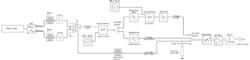
The SDR itself contains an RFE with receive (Rx) and transmit (Tx) functions to handle signals over a wide tuning range, which is accomplished using various mixing stages in both analog and digital. In addition, these radio chains offer very high bandwidths of up to 3 GHz per radio chain and up to 16 fully independent radio chains per SDR.
The SDR’s digital backend contains a high-performance Arm CPU/FPGA with onboard DSP capabilities for modulation, demodulation, digital upconversion (DUC), digital downconversion (DDC), filtering, etc. Furthermore, SDRs are highly reconfigurable and upgradable to the latest radio protocols, DSP algorithms, IP cores, etc.
The FPGA also contains the means to packetize data into Ethernet packets and transport it over SFP+/qSFP+ links over 10- to 100-Gb/s links. These devices come with an API to develop/control the radio system via a host system, as well as signal-processing development toolkits such as GNU Radio.
Basics of RFSoC
Traditional system-on-chip (SoC) technologies were designed specifically for their use case, such as Bluetooth, Zigbee, Wi-Fi, and even mobile phone chips (GPS, etc.), all of which were reduced to a small-scale transceiver design. As with most electronics, size has decreased while functionality is on the rise, as can be seen in one of the latest developments in transceivers—the RF system-on-chip (RFSoC). These transceivers or fully integrated SoC dedicated chips were developed by Xilinx and premiered in 2017.
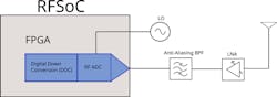
In particular, RFSoC devices essentially embed RF-class multichannel analog-to-digital converters (ADCs) and digital-to-analog converters (DACs) with Xilinx’s multiprocessor system-on-chip (MPSoC) as well as an Arm processor enhanced FPGA. As shown in Figure 2, the architecture integrates the mixed-signal’s interface (ADC/DAC) into the signal chain. These devices use a direct sampling ADC/DAC with DDC and DUC.
Pros and Cons of RFSoCs
A significant benefit of RFSoCs is their lower power consumption. The driving factor behind the reduced power of RFSoCs is the need for fewer boards, and the elimination of the interfaces required to connect the various ICs in a discrete solution.
One such common serial interface standard is JESD204B, which has been eliminated from the Xilinx RFSoC product line. With the RFSoC, data converters are integrated directly into the FPGA using parallel interfaces, and thus, these devices don't require the high-pin-count external connections needed for discrete parallel interface converters.
In addition, RFSoCs don’t have the latency associated with a JESD204 serial interface. This makes them an attractive solution for low-power, multichannel-count, and low-latency applications. Cost-effectiveness also is a benefit of SoC transceivers in applications requiring limited functionality, which as mentioned, are integrated on a single chip. In these applications, RFSoC devices need only a few support circuits, such as a microprocessor for control, a power supply, and an antenna(s).
While RFSoC devices are impressive and can be advantageous in a number of applications, they also have multiple disadvantages. As RFSoCs/DFEs are essentially chips with embedded direct-sampling data converters, an engineer often needs to design a printed circuit board (PCB) around the RFSoC to increase capabilities as well as house the boards in some sort of enclosure (for environmental or ruggedization, for instance). Such a dense design of data converter interfaces creates many challenges.
For starters, numerous issues exist when it comes to signal integrity on the RFSoC, including spurious digital-signal pickups, crosstalk between channels, matters related to impedance matching, and issues of thermal management. Much of this can’t be avoided, particularly at higher frequencies where these effects are more visible. That’s why the most sophisticated RFSoCs currently on the market only have tuning ranges up to 7.1 GHz.
Moreover, the timing and synchronization between new board components (PLLs, NCOs, LOs, etc.) will all need to be integrated with the RFSoC, where timing/alignment is only considered in the digital domain. However, the PCB layout must be designed to consider the latency requirements of the RFSoC.
Many challenges also crop up when developing the FPGA “firmware” code for the RFSoC/SoC/DFEs, because you need to be widely familiar with programming in hardware descriptive language (HDL), plus various other embedded-system design programming, to have a functional radio/DSP system. For instance, if you’re trying to design a custom modem, implement some sort of packetization standard (i.e., to transfer data over Ethernet in VITA 49 packets), or develop a custom signal processor, a lot of development time will be required.
Pros and Cons of SDRs
As can be gathered from the discussion on RFSoCs, lots of development is usually required to get a functional wireless technology up and running. Thus, an already-developed SDR (i.e., has an API, works with DSP development toolkits, already passes data from the transceiver to a host-system-computer/storage devices, uses VITA 49 packet formats, etc.) can significantly reduce time to market or setup for a particular application.
For SDR manufacturers that use a dedicated analog RFE, the possibility remains to build custom designs that entail many performance benefits. There’s lots of flexibility when you build out your entire radio chain using discrete commercial off-the-shelf (COTS) ICs (amplifiers, filters, attenuators, mixers, etc.) that can be optimized for particular RF performance requirements.
For instance, the RFE can be customized for various performance requirements (tuning range, elimination of spurs within a band, output power, etc.). Another advantage of using an SDR with discrete components is that you can bypass numerous components in the RFE, which isn’t possible with RFSoCs. On top of that, the SDR’s RFE allows for higher tuning ranges (due to multiple mixer stages/multiple RFE signal chains). And in certain applications, it’s often possible to design an SDR that conforms to a particular size, weight, and power (SWaP) specification.
In terms of FPGA resources, on high-performance SDRs like Per Vices’ Cyan platform, feature many more logic elements/cells. These SDRs contain 5.5 million logic elements compared to the maximum of 930,000 currently available on RFSoC. Also, when working with an SDR manufacturer, it becomes possible to implement custom HDL code in a much less time-consuming and cost-effective manner compared to having to develop in-house.
The ease of use is worth mentioning, too. With most SDRs, data from the FPGA is passed over qSFP+ ports to a host system that has a number of different UIs to control the actual radio (for instance, with GNU Radio, Web UIs) and maintains compatibility with UHD for development in C++, GNU Radio, or Python.
Thus, when using or integrating an SDR into a wireless system, you’re able to focus on developing your application on it, rather than working out how to make the device operate as a radio device in the first place. In fact, many manufacturers of SDRs use SoCs in their digital backend and develop their analog RFE and other PCBs and APIs around these.
Of course, SDRs do come with some disadvantages. For one, these devices tend to be more expensive than many RFSoC/SoC DFEs. Moreover, high-end SDR devices often use larger FPGAs and JESD transceivers between data converters, and thus consume considerable power (albeit, this can be optimized for various requirements). Another disadvantage of some SDRs is the size/form factors of such devices. While it’s possible to make custom chassis/form factors for an SDR, these are generally much larger than small-form-factor RFSoCs/SoCs.
Suitable Applications for Each Transceiver Type
RFSoCs are currently being marketed to work with 4G/5G base station equipment and other small-form-factor/low power consumption wireless systems. 5G base stations are often good applications of RFSoCs, particularly in remote radio head units (RRUs) in small-cell deployment due to the need for a very small form factor. Other applications include LiDAR for autonomous-vehicle technologies, as well as unmanned aerial vehicles (UAVs)/unmanned underwater vehicles (UUVs) that require low-power wireless communications.
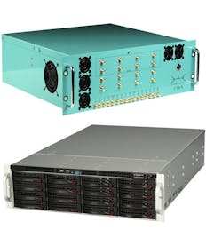
On the other hand, SDRs are useful for wide instantaneous-bandwidth (IBW) applications, such as spectrum monitoring and recording, which can be combined with storage and playback solutions (Fig. 3). In addition, for a large swath of radar and satellite communications in higher frequencies, such as Ka- or Ku-bands, the higher tuning range of an SDR often is necessary.
The analog RFE also is much better suited for applications requiring better wide-band dynamic range and/or spurious-free dynamic range (SFDR), such as in electronic-warfare (EW)/SIGINT applications. And when it comes to easier prototyping, SDRs likely are the better option, due to their ease of use with platforms such as GNU Radio and other DSP toolkits. They allow for much easier modification/redesign thanks to their simple interface, compared to having to develop a custom API or HDL code when using an RFSoC.
Conclusion
RFSoCs, DFEs, SDRs, transceivers—these are the many names for devices that do essentially the same thing: transmit and receive signals. There are numerous advantages and disadvantages of these devices. Furthermore, your application will determine how much time/money and resources you have to spend on development, as well as the SWaP requirements of such applications. As discussed, a high-performance SDR and an RFSoC are very different, and each has their pros and cons.
About the Author
Brendon McHugh
Field Applications Engineer, Per Vices Corp.
Brendon McHugh has a degree in theoretical and mathematical physics from the University of Toronto and works at Per Vices as a Field Applications Engineer and Technical Writer.
Comment About the Article
To join the conversation, and become an exclusive member of Electronic Design, create an account today!

Leaders relevant to this article: