RF Demystified: The Different Types of Scattering Parameters

Members can download this article in PDF format.
What you'll learn:
- What are S-parameters?
- The multiple types of S-parameters beyond the small-signal variety.
Scattering parameters (S-parameters), which describe the fundamental characteristics of RF networks, come in many flavors, including small signal, large signal, pulsed, cold, and mixed mode. They quantify how RF energy propagates through a system and thus contain information about its fundamental characteristics.
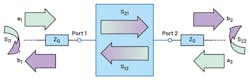
Using S-parameters, we can represent even the most complex RF device as a simple N-port network. Figure 1 shows an example of a two-port unbalanced network, which can be used to represent many standard RF components such as RF amplifiers, filters, or attenuators, to name a few.
The wave quantities, schematically shown in Figure 1, are complex amplitudes of the voltage waves incident on Port 1 and Port 2 of the device. If we stimulate one port at a time with the corresponding wave quantity a1 or a2 when the other port is terminated into the matched load, we can define the forward and reverse responses of the device in terms of the wave quantities b. These quantities represent voltage waves reflected from, and transmitted through, the ports of the network.
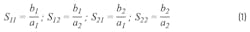
If we take the ratio of the resulting complex responses and the initial stimulus quantities, the S-parameters of a two-port component can be defined as shown in Equation 1:
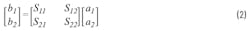
The intrinsic response of the network can then be expressed by grouping S-parameters together into a scattering matrix (S-matrix), which relates the complex wave quantities at all its ports. For the two-port unbalanced network, the stimulus-response relation will obtain the form in Equation 2:
The S-matrix can be defined in a similar manner for an arbitrary N-port RF component.1,2
Types of S-Parameters
Small Signal
If not explicitly stated otherwise, the term “S-parameters” usually refers to the small-signal S-parameters. They represent an RF network response to a small signal-stimulus quantifying its reflection and transmission characteristics over frequency in a linear operational mode. Using small-signal S-parameters, we can determine basic RF characteristics including voltage standing wave ratio (VSWR), return loss, insertion loss, or gain at given frequencies.
Large Signal
However, if we continuously increase the power level of a signal that’s passing through an RF device, it will often result in more pronounced nonlinear effects. These effects can be quantified using another type of scattering parameter called large-signal S-parameters. They vary not only across different frequencies, but also across different power levels of a stimulus signal. This type of scattering parameter can be used to determine nonlinear characteristics of a device such as its compression parameters.
Both small- and larger-signal S-parameters are usually measured using continuous-wave (CW) stimulus signals and applying a narrowband response detection. However, many RF components are designed to be operated with pulsed signals, which have a broad frequency-domain response. This makes it challenging to accurately characterize an RF component using the standard narrowband detection method.
Pulsed
Therefore, for the characterization of devices in a pulsed mode, the so-called pulsed S-parameters are typically utilized. These scattering parameters are obtained using special pulse-response-measurement techniques.3
Cold
Another type of S-parameter, which is rarely talked about, but which might sometimes become important to consider, is cold S-parameters. The term “cold” means that the scattering parameters are obtained for an active device in a nonactive mode (i.e., when all of its active elements are inactive; for example, transistor junctions are reverse- or zero-biased and no transfer currents flow). This type of S-parameter can be used, for instance, to improve matching of the signal-chain segments with off-state components that cause high reflections in the signal path.
Mixed Mode
Up until now, we’ve defined S-parameters for a typical single-ended component when the stimulus and response signals are referenced to ground. However, for balanced components that have differential ports, this definition isn’t sufficient. Balanced networks require a broader characterization approach, which must be able to fully describe their differential- and common-mode responses.
This can be achieved by using mixed-mode S-parameters. Figure 2 shows an example of the mixed-mode scattering parameters grouped together into an extended S-matrix representing a typical two-port balanced component.
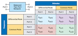
Subscripts of the mixed-mode S-parameters in this matrix use the naming convention b-mode, a-mode, b-port, and a-port. The former two describe the modes of the response port (b-mode) and stimulus port (a-mode), and the latter two specify index numbers of these ports, where b-port corresponds to the response and a-port to the stimulus port.
In our example, the port modes are defined either by the subscript d—differential—or c—common mode. However, in a more general case of a component that has both balanced and unbalanced ports, a mixed-mode S-matrix also will have additional elements with subscript s describing the quantities obtained for the single-ended ports.
The mixed-mode scattering parameters enable us to determine the basic parameters of an RF component such as return loss or gain. In addition, they make it possible to determine the key figures of merit used to characterize performance of the differential circuits, such as common-mode rejection ratio (CMRR), magnitude imbalance, and phase imbalance.
Conclusion
This article presented basic definitions and briefly discussed the key types of scattering parameters. The S-parameters can be used to describe fundamental characteristics of RF components at different frequencies and for different power levels of a signal.
The development of RF applications relies on the use of S-parameter data describing integral structures and constituent components of RF designs. RF engineers measure or rely on already existing S-parameter data, which is typically stored in standard text files known as Touchstone or SnP files. These files are often freely provided for the most popular RF components available on the market today.
References
1. David Pozar, Microwave Engineering, Fourth Edition. Wiley, 2011.
2. Michael Hiebel, Fundamentals of Vector Network Analysis. Rohde & Schwarz, 2007.
3. “Pulsed Measurements Using Narrowband Detection and a Standard PNA Series Network Analyzer,” Keysight Technologies, December 2017.
About the Author
Anton Patyuchenko
Field Applications Engineer
Anton Patyuchenko received his Master of Science in microwave engineering from the Technical University of Munich in 2007. Following his graduation, Anton worked as a scientist at German Aerospace Center (DLR). He joined Analog Devices as a field applications engineer in 2015 and is currently providing field applications support to strategic and key customers of ADI specializing in RF applications.
Comment About the Article
To join the conversation, and become an exclusive member of Electronic Design, create an account today!

Leaders relevant to this article: