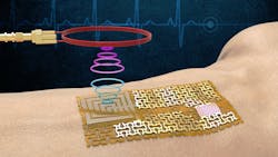
Go Ahead and “Sweat It” for Energy Harvesting and Biosensing
What You’ll Learn
- Why sweat is such a useful fluid for electronics.
- How sweat can be used for energy harvesting.
- How sweat can be used for biosensing.
Regardless of your personal feelings about human sweat, the facts are that it’s a biological necessity, it’s ubiquitous, it’s accessible, and it’s free. Even better, the chemical composition of sweat can be leveraged for a variety of uses, including energy harvesting, dynamic biosensing, and more. Proof is in a trio of recent research projects from a variety of institutions.
1. Sweat-based energy harvesting
Although not energy harvesting in the customary sense, a team at the University of Massachusetts (Amherst) has developed a microbial biofilm as a cohesive, flexible material for long-term continuous electricity production using the evaporation of water or sweat. The single biofilm sheet, about 40 µm thick, is the core functional component and continuously produces power with a density of about 1 μW/cm2, much higher than that achieved with thicker engineered materials.
This biofilm is produced naturally by an engineered version of the bacteria Geobacter sulfurreducens, which is known to produce electricity and has been used in microbial batteries. However, these batteries require that the bacteria is “fed” a constant diet. By contrast, this new biofilm can supply as much, if not more, energy than a comparably sized battery and works continuously because it’s dead and so doesn’t need to be fed (Fig. 1).
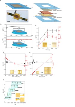
1. (a) Schematic and actual photo (bottom) of a biofilm device. Scale bar, 0.5 mm. (b) Representative open-circuit voltage Vo (top) and short-circuit current Isc (bottom) from a device placed on a water surface (schematics). The device size was 5 × 5 mm2. (c) Vo (black) and Isc (red) from devices with respect to different porosities in the mesh electrodes. The pore size was kept at 100 µm and the device sizes were 25 mm2. (d) Vo (black) and Isc (red) from devices with fixed porosity of 0.4 but varying pore sizes (from 1,000 to 20 µm) in the mesh electrodes. The device sizes were 25 mm2. At the pore size of 20 µm, the estimated optimal energy density (Vo·Isc/4) was ~0.84 µW/cm2 in the active biofilm region. (e) Vo (black) and Isc (red) from devices of different areas, with the porosity and pore size in the mesh electrodes, kept 0.4 and 100 µm. (f) Measured Vo from devices connected in series (upper inset) using a “buckle” design in electrodes (bottom schematic).
G. sulfurreducens grows in colonies that look like thin mats; each of the individual microbes connects to its neighbors through a series of natural nanowires. The team then harvests these mats and uses a laser to etch small circuits into the films. After the films are etched, they’re sandwiched between electrodes and finally sealed in a soft, sticky, breathable polymer that you can apply directly to your skin (Fig. 2). Once this tiny battery is “plugged in” by applying it to your body, it can power small devices.
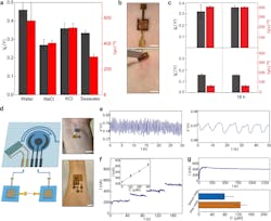
2. (a) Open-circuit voltage Vo (gray) and short-circuit current Isc (red) from biofilm devices placed on deionized water, 0.5 M NaCl, 0.5 M KCl, and artificial seawater (475.7 mM NaCl, 10.8 mM CaCl2, 25.6 mM MgCl2‧6H2O, 28.2 mM MgSO4) solutions. (b) A biofilm device was patched on the skin (top) and removed 18 hours later (bottom). Scale bars, 0.5 cm. (c) Vo (gray) and Isc (red) from biofilm devices patched on sweating skin (top) and dry skin (bottom), before (left) and after (right) 18 h. (d) (left) schematic of connecting biofilm devices to wearable sensors for wearable powering. (right) Actual photos of powering a skin-wearable strain sensor with one biofilm device (top) and an electrochemical glucose sensor with three biofilm devices (bottom). Scale bars, 1 cm. (e) Measured pulse signal (left) from the wrist and respiration signal (right) from the chest using the biofilm-powered strain sensor. (f) Amperometric responses from a biofilm-powered glucose sensor placed in solutions having glucose concentrations (C) of 0, 100, 200, and 300 µM, respectively. The inset shows the calibrated response curve. (g) (top) A continuous measurement of current from a biofilm-powered glucose sensor during exercise. (bottom) Calibrated glucose levels from collected measurements before (blue) and after (orange) a meal.
The work is detailed in their paper “Microbial biofilms for electricity generation from water evaporation and power to wearables” published in Nature Communications; a detailed Supplementary File is posted as well.
2. Glucose biosensor
Researchers at Ohio State University have successfully tested a battery-free, wireless biochemical sensor that detected the blood sugar—or glucose—humans excrete from their skin when they exercise. Such chemical biomarkers can indicate changes in a person’s health.
The topology uses a resonant circuit, which reflects RF energy sent out by an external reader system. The coupling between a sensing interface and an inductor-capacitor oscillator through a pair of varactor diodes converts a change in electric potential into a modulation of the capacitance, resulting in a quantifiable shift of the resonant circuit.
The researchers acknowledge the challenges. State-of-the-art digital wireless schemes usually require integrated electronic components with non-ideal form factors for signal generation/transmission.
While passive sensors working based on resonant inductive coupling have merits due to the simple configuration and light weight, conventional designs typically have the responsive elements integrated within the LC circuit. As a result, it’s difficult to eliminate artifacts caused by interactions between the electromagnetic coupling unit and target biotissues/biofluids.
Instead, they developed a modularized LC circuit model where the varactor pair separates the device into two key functional parts: a stretchable biochemical sensing interface (dc part) to be in contact with target biofluids and a loop antenna as the coupling unit (ac part) for wireless signal transmission (Fig. 3). Stretchable wires connecting the dc and ac parts can effectively distribute mechanical strains and protect functional components from deformations.
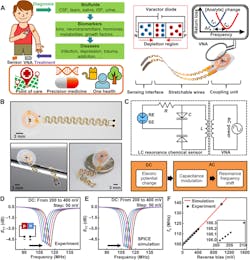
3. Design and working principle of the tuning circuit–inspired wireless biochemical sensors: (A) Schematic illustration of the stretchable, battery-free sensor and envisioned applications of the sensor system in detecting various biomarkers in bodily fluids. (ISF = interstitial fluid). (B) Photographs of a wireless sensor. (C) Equivalent circuit and flowchart for the signal-conversion and transmission process of the sensor system. (D,E) Measured and simulated shift of resonance curves of a sensor with a dc reverse bias (from 200 to 400 mV; step: 50 mV). (F) Measured and simulated results of fs as a function of the reverse bias (inset: zoom-in view).
The interaction between analytes and the corresponding biorecognition elements creates a potential difference across the two electrodes in the dc part that scales with the concentration of target biochemical species. This potential provides the reverse bias for the two series varactor diodes.
The researchers note than this system works a frequency-modulation (FM) mechanism for chemical sensing by converting changes in electric potential into modulation in capacitance using the varactors (Fig. 4). This in contrast to amplitude-modulation schemes that rely on tuning the Q factor of the circuit.
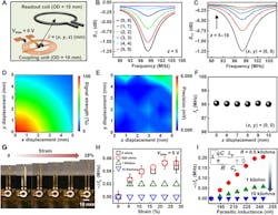
4. Working range and mechanical properties of the biochemical sensors: (A) Schematic illustration of the relative position of the sensing platform and the readout coil. (B,C) Resonance curves with varied lateral (B) and vertical (C) distance between the electromagnetic coupling unit and the readout coil. (D,E) Signal strength (D) and measurement precision (E) as a function of the lateral distance from the origin (z = 5 mm). (F) fs as a function of the vertical distance (x = y = 0). (G) Photographs of a stretchable sensor with a tensile strain (from 0 to 28%) applied to the serpentine wires. (H) Measured results of fs as a function of the damping resistance and applied strain. (I) Spice simulation results of fs as a function of the parasitic inductance (Lp) and damping resistance (inset: equivalent circuit used for simulation).
Although the magnitude of the resonance curve depends on the orientation and distance between the electromagnetic coupling unit and the readout coil that affect the coupling coefficient, the frequency shift is due to an intrinsic property of the resonance circuit and is relatively independent of the variation. Thus, it can provide reliable wireless signal transmission despite a slight misalignment between the coupling unit and primary coil.
They used the arrangement to provide real-time monitoring of glucose in sweat during field testing. While it’s not possible to provide a single number quantifying the results, their tables and data show a fairly accurate and dynamic assessment of sweat glucose levels.
The work, including results and analysis, is detailed in a paper published in Science Advances, “Battery-free, tuning circuit-inspired wireless sensor systems for detection of multiple biomarkers in bodily fluids,” along with a lengthy Supplementary Materials file that provides extensive background on the design on materials, fabrication, electronics, and Spice models, plus additional results.
3. Wireless electronic skin biosensor
But why stop there when there’s so much more that skin sensing can reveal? An MIT-based team notes that recent advances in flexible and stretchable electronics have led to a surge in health-monitoring platforms based on electronic skin.
However, many of these conventional wireless e-skins rely on rigid ICs that compromise the overall flexibility and consume considerable power. On the other hand, “chip-less” wireless e-skins based on inductor-capacitor resonators are limited to mechanical sensors with low sensitivities.
To overcome these limitations, they developed a chip-less wireless e-skin based on surface-acoustic-wave (SAW) sensors made of freestanding, ultra-thin, single-crystalline, piezoelectric gallium-nitride (GaN) membranes using a technique called remote epitaxy (Fig. 5). They peeled away ultra-thin single-crystalline films of GaN, which in its pure, defect-free form is a highly sensitive piezoelectric material, and used this pure film as both a sensor and a wireless communicator of surface acoustic waves.
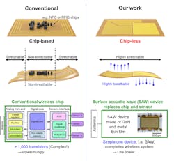
5. Comparison between conventional chip-based wireless e-skin and chip-less wireless e-skin in this work. For conventional e-skins, chips are crucial for converting analog signals from the sensors to digital signals and sending them through the antenna wirelessly.
The main advantage is that the material is flexible and breathable, thus providing better comfort. The devices convert electrical energy into SAWs using a piezoelectric resonator. The resonator is sensitive to changes in strain, mass changes due to the absorption or loss of ions, and ultraviolet light, all of which can be used for different sensing measurements.
The researchers hypothesized that a GaN-based sensor, adhered to the skin, would have its own inherent, “resonant” vibration or frequency that the piezoelectric material would simultaneously convert into an electrical signal, the frequency of which a wireless receiver could register. Any change to the skin’s conditions, such as from an accelerated heart rate, would affect the sensor’s mechanical vibrations as well as the electrical signal that it automatically transmits to the receiver (Fig. 6).
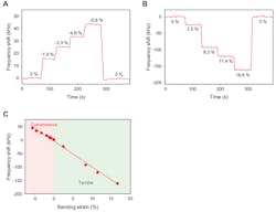
6. Real-time output responses and characteristics of GaN SAW e-skin strain sensors under (A) compressive strain and (B) tensile strain. (C) Output response depending on strain.
The researchers also investigated the RF and power characteristics of their arrangement, including measurement of total power consumed while making a wireless measurement using their SAW sensor (Fig. 7).
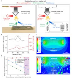
7. Estimation of total power consumed during wireless measurement using a SAW sensor. (A) Schematic illustration of the total power consumption. Radiated power from reader coil is consumed as free-space path loss, SAW tag coil loss, and SAW sensor consumption. (B) Measured impedance (Z = R + jX, where Z, R, and X are impedance, resistance, and reactance, respectively) values of the SAW sensor that were used for power consumption calculation. (C) Simulated magnitude (top) and direction (bottom) of H-field during wireless power transfer from reader coil to SAW tag coil, obtained using Ansys HFSS finite element analysis. (D) Estimation of energy consumption per measurement for each component in (A) as functions of the distance between reader coil and SAW tag coil.
You can read their paper “Chip-less wireless electronic skins by remote epitaxial freestanding compound semiconductors” published in Science. They also posted a lengthy, highly detailed Supplementary Materials file that includes considerable additional information as well as a table comparing their technique to others, plus a video.
About the Author

Bill Schweber
Contributing Editor
Bill Schweber is an electronics engineer who has written three textbooks on electronic communications systems, as well as hundreds of technical articles, opinion columns, and product features. In past roles, he worked as a technical website manager for multiple topic-specific sites for EE Times, as well as both the Executive Editor and Analog Editor at EDN.
At Analog Devices Inc., Bill was in marketing communications (public relations). As a result, he has been on both sides of the technical PR function, presenting company products, stories, and messages to the media and also as the recipient of these.
Prior to the MarCom role at Analog, Bill was associate editor of their respected technical journal and worked in their product marketing and applications engineering groups. Before those roles, he was at Instron Corp., doing hands-on analog- and power-circuit design and systems integration for materials-testing machine controls.
Bill has an MSEE (Univ. of Mass) and BSEE (Columbia Univ.), is a Registered Professional Engineer, and holds an Advanced Class amateur radio license. He has also planned, written, and presented online courses on a variety of engineering topics, including MOSFET basics, ADC selection, and driving LEDs.
Comment About the Article
To join the conversation, and become an exclusive member of Electronic Design, create an account today!

Leaders relevant to this article: