The Origin, Explanation, and Applications of Triple-Five Timers
This article is part of Electronic Design's 70th Anniversary series.
What you’ll learn:
- The history of the 555 timer.
- What are the 555's modes of operation?
- About my book to help teach those young and old about 555 timers.
- element14’s 555 timer contest.
The 555 timer celebrated the 51st anniversary of its creation in 1971 by electronics engineer Hans Camenzind, who was tasked by electronics manufacturer Signetics to develop a phase-locked-loop (LLP) IC. A few days after the initial design, Camenzind thought of using a direct resistance instead of a constant-current source, finding that the revision was more efficient.
That led to a decrease of the required nine external pins to eight, enabling the IC to fit in an 8-pin package instead of a 14-pin package. This revised version passed a design review, and the prototypes were completed in October 1971 as the NE555V (plastic DIP) and SE555T (metal TO-5), designs that are still in use today.
555 timers are monolithic ICs that provide signals to a digital system to change its state. They also can be used as a multivibrator or a form of oscillator, which has two stages and can be output by either of the states. In essence, it's two amplifier circuits arranged with regenerative feedback.
Genesis of the “555” Moniker
The timer takes its name from the fact that the original model packed three resistors, rated at 5 kΩ each. However, Camenzind has stated, "It was just arbitrarily chosen. It was Art Fury (marketing manager) who thought the circuit was gonna sell big who picked the name '555'."
To that end, two types of 555 timers are in use today, both being eight-pin chips. The most common is the rectangular “V” package, which has four pins down each side. The other version, which used to be the most common but has now fallen somewhat from favor, is the circular “T” package.
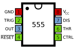
Each of the eight pins provides the following functions (Fig. 1):
- Ground: Acts as a safety measure similar to plugs for wall outlets.
- Trigger: Passes on voltage to start timing operations.
- Output: Carries voltage to the device using the timer.
- Reset: Ends the timing operation.
- Control Voltage: An optional pin for controlling the circuit outside the main setup.
- Threshold: Determines how long the timer should output voltages during each On/Off cycle.
- Discharge: Usually connected to a capacitor, also influences the timing interval.
- V+: Inputs voltage.
What’s Inside the 555?
Next, we’ll look at the 555 timer's internal circuitry and indicate what each symbol means in the block diagram above (Fig. 2). In the center are a pair of comparators denoted by their upside-down triangle symbols. These are used to compare two voltages or currents and output a digital signal that indicates which is larger. In addition, a flip-flop, symbolized by a rectangle, is a circuit that has two stable states and can be used to store simple information. The timer also packs a voltage divider, a discharge transistor, and an output stage.
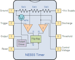
The voltage divider (shown at the top of the diagram) features a trio of 5-kΩ resistors connected together. It provides reference voltages at 1/3 and 2/3 of the supplied voltage, which can range from 5 to 15 V. This is where those comparators come into play, as they compare two analog input voltages at their positive (non-inverting) and negative (inverting) input terminal.
For example, if the input voltage at the positive terminal is higher than the input voltage at the negative terminal, the comparator will output 1. Alternatively, if the voltage at the negative input terminal is higher than that at the positive terminal, the comparator will output 0.
The first comparator negative input terminal is connected to the 2/3 reference voltage at the voltage divider and the external Control pin (Pin 5), while the positive input terminal is connected to the external Threshold pin (Pin 6). Moreover, the second comparator negative input terminal is connected to the Trigger pin (Pin 2), while the positive input terminal is connected to the 1/3 reference voltage at the voltage divider.
By taking advantage of those three pins, users can control the output of the two comparators, which are then piped to the R and S inputs of the flip-flop. The flip-flop will then output 1 when R is 0 and S is 1; inversely, it will output 0 when R is 1 and S is 0. Moreover, the flip-flop can be reset via the Reset pin (Pin 4), which can then override the two inputs and thus reset the entire timer at any given time.
The Q-bar output of the flip-flip goes to the output stage or the output drivers, allowing it to either source or sink a current of 200 mA to the load. The output of the flip-flop also is connected to a transistor that connects the Discharge pin (Pin 7) to the Ground.
Quick Modes Refresher
A 555 timer can be employed in several different ways. For instance, a monostable operation, where the output signal switches between the default off position and a temporary on position at regular intervals, is most commonly used for timers. This configuration consists of one stable and unstable state. If the stable output is set at high, then the output of the timer is high.
An astable operation is when the output voltage rises and falls in a set pattern, essentially making it an oscillator. As the pattern can be varied, it can be used for any purpose that requires a particular tone or wave pattern. In this mode, there will be no stable level at the output, and the output will keep swinging between high and low. This means it doesn't have any stable state and keeps switching between high and low without the application of any external trigger.
Finally, bistable operation is when the signal can be held in one of two positions, meaning the 555 timer can act as the smallest possible computer memory unit. In this configuration, both the output states are stable. At each interrupt, the output changes from low to high and vice versa. For example, if there’s a high output, it will go low once it receives an interrupt and stays low until the following interrupt changes the status.
555 Timer Applications
There are a vast number of 555 timer applications that span a ton of industries, including for PWM pulse-width modulation (PWM) and pulse-position modulation (PPM), which are widely used in controlling servos, amplifiers, and telecommunications. They also can be implemented for light dimmers, accurate time delays, digital logic probes, and analog frequency meters. Moreover, they will find homes in tachometers; dc-dc converters; dc voltage regulators; voltage-to-frequency converters; and pulse, waveform and square wave generation, among others.
On top of that, 555 timers can be integrated for use with cable testers, vehicle wiper speed controls, a timer switch, time delay generation, a monostable multivibrator, and an astable multivibrator. While there are a ton of commercial applications for the 555 timer, a myriad of custom projects use the chip in one form or another, too. Below are several novel examples of what can be done using the variable timer.
Personal Experience
I truly love the 555-timer IC. Excuse the sudden switch to first person here.
The chip is essentially my first step into the world of being an electrical engineer. It was the first time I realized I could make just about anything without the need to know programming languages. A blinking light led to an electronic switch to storing an alert notification—if someone opened an electronically monitored box.
Flash forward 30-some-odd years later, and I write a book on the subject. It's called Essential 555 IC: Design, Configure, and Create Clever Circuits from The Pragmatic Bookshelf (Fig. 3).
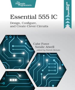
My goal was originally to teach my son how to use a 555 timer. However, I soon realized an approach with cascading project complexity could let anyone learn how to use the IC through hands-on project builds.
I asked my publisher for the maximum discount they will give—I got 40% off! Use the coupon code “catimers40” at The Pragmatic Bookshelf.
Coincidentally, the engineer and maker community element14 is having a contest. They’re asking for people to send in their craziest 555 timer-based project ideas in The 555 Timer Madness. Head on over there and submit your idea. You can win a $200 or $100 shopping cart! Don't worry, I won't be competing in this contest.
I'm a content producer at element14, so think of me as more of a project professor, guiding you along the way. Feel free to reach out to me at element14 if you have questions about 555 timers or about building projects from my book. My handle on element14 is @catwell
51 years young—the 555 timer IC is still worth using.
Read more articles in Electronic Design's 70th Anniversary series.
About the Author

Cabe Atwell
Technology Editor, Electronic Design
Cabe is a Technology Editor for Electronic Design.
Engineer, Machinist, Cartoonist, Maker, Writer. A graduate Electrical Engineer actively plying his expertise in the industry and at his company, Gunhead. When not designing/building, he creates a steady torrent of projects and content in the media world. Many of his projects and articles are online at element14 & SolidSmack, industry-focused work at EETimes & EDN, and offbeat articles at Make Magazine. Currently, you can find him hosting webinars and contributing to Electronic Design and Machine Design.
Cabe is an electrical engineer, design consultant and author with 25 years’ experience. His most recent book is “Essential 555 IC: Design, Configure, and Create Clever Circuits”
Cabe writes the Engineering Life & Engineering on Friday blog on Electronic Design.
See Cabe's cartoons & comic strips here.
Comment About the Article
To join the conversation, and become an exclusive member of Electronic Design, create an account today!

Leaders relevant to this article: