What’s All This Noise Stuff, Anyhow? (Part 1)

Recently I was invited to a meeting to see the results of a new high-performance, low-noise transistor project. I looked at the technical report. The new transistors were indeed quieter than the old ones. In fact, they were two to four orders of magnitude quieter than the conventional ones. I was suspicious. What was the test method? Oh, here is the test circuit (see the figure).
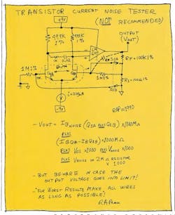
Now, I asked, were the betas high or low? I was told they were pretty low, but they can be brought up later. I explained that when the betas get low, if they’re not very well matched, the test circuit’s output can peg—right at the + or – rail. Then, of course, the apparent output noise gets rather small. (Ohhhhh!)
When this circuit is running okay, the current noise is amplified by a big resistance: 1 MΩ X (N+1), where N is the closed loop gain, (RF/R1). So, the output will include: (1+ noise of Q1A) + (I-noise of Q1B) X 1000 MΩ. However, the offset current (I+) – (I-) will also be magnified by 1000 MΩ. So even 9 nA of offset current will cause the op amp’s output to try to go to +9 V. If the power supply won’t let the output get to a fair balance, the output will peg. Naturally the output becomes very quiet—the circuit has stopped amplifying the noise.
I also pointed out that ideally the circuit could measure the base-current noise of the transistor, or device under test (DUT). But the layout of the circuit is quite critical. Just 1 pF of capacitance (CF) from the output to the base of Q1B will cause a lag in the response: 1000 MΩ X 1 pF = 1 ms, so the noise will roll off above 160 Hz. You can make a layout with less than 0.1 pF, but you have to think about it and engineer it.
When we checked the test box, it was laid out very neatly: The output wire was bused alongside the summing-point (base of Q1B) wire, and the bandwidth was indeed less than 100 Hz. In a future column, I will talk about what a picofarad looks like and the harm it can do to you. So, even if the output wasn’t pegged and you looked for the noise at 1 or 10 kHz, this test circuit would give an answer that’s considerably quieter than the theoretical minimum for the transistor. Now here’s a good place for a sanity check.
It’s not impossible to measure the noise of a transistor’s base circuit, but you must have a suitable circuit. I wrote a paper back in 1968, and as I look at it today, the only things that changed are the names of the op amps. You can’t buy any of those old discrete transistor, potted module op amps any more, but the testing approaches are just as valid. Maybe I’ll write an updated version. In this case, the problem was that a 1-MΩresistor and a noise gain of 100 or 1000 (provided by RF and R1) wasn’t a good idea. The stray capacitances and the noise of the 1 MΩ are detrimental to accuracy. It’s better to use a real 100-MΩ or 1000-MΩ resistor.
In fact, a 20-MΩ or 5-MΩ resistor is justified because it will still give plenty of signal-to-noise ratio, and a lot more bandwidth. More on how to do this in the next issue.
All for now. / Comments invited! / RAP / Robert A. Pease / Engineer
About the Author

Bob Pease
Bob obtained a BSEE from MIT in 1961 and was a staff scientist at National Semiconductor Corp., Santa Clara, CA, for many years. He was a well known and long time contributing editor to Electronic Design.
We also have a number of PDF eBooks by Bob that members can download from the Electronic Design Members Library.
Comment About the Article
To join the conversation, and become an exclusive member of Electronic Design, create an account today!

Leaders relevant to this article: