Reliable Power Switch for Privacy Apps Has Offline Memory

Members can download this article in PDF format.
What you'll learn:
- How to implement a more secure power switch, replacing a mechanical toggle switch, for multiple applications.
- Components involved in setting up the power switch.
- Specifics of macrocell operation.
Today, privacy concerns are being raised more often than ever before. Big tech companies are constantly being accused of secretly gathering users' personal information and even selling it to third-party entities.
In times when nearly every household has at least one gadget with a camera and microphone, besides smartphones, people start thinking twice about the trust they give to the manufacturer and service provider before buying another device. A huge number of cases involve cameras that were hacked and controlled remotely. People began installing external camera covers and taping a microphone hole.
To solve this problem, a mechanical toggle switch can be installed on a camera/mic by the manufacturer, ensuring protection against hackers as well as serving as a visual indicator of the on/off state. However, the downside is the bad design and ergonomics of such solutions.
The circuit described in this article is designed for devices that need to prioritize privacy. For example, in gadgets with a camera and/or microphone, the user has to be sure that the camera (microphone) is turned off if desired, even after the gadget was powered off and on again for a long period. Also, if someone with bad intentions wants to hide the fact that the camera (microphone) is on by removing the LED indicator (or shortening it), the camera (mic) will be turned off automatically.
The circuit isn’t connected to the gadget’s processor, making it impossible to hack in and turn on/off the camera and/or microphone remotely.
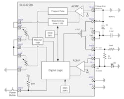
Essentially, this circuit is a replacement for the mechanical toggle switch; however, it uses a tiny pushbutton that allows for easy integration into the gadget’s design. See the block diagram in Figure 1 and the Go Configure Software Hub’s GreenPAK Designer project in Figure 2 (the design file is available here).

Design Operation: Schematic Design
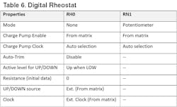
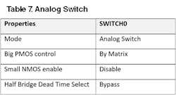
The AnalogPAK SLG47004 has two digital rheostats that can be configured as one digital potentiometer. One of its features is the ability to store its value after powering off. This feature is used in the current design as a 1-bit memory cell. Each time the button is pressed, the potentiometer RH0RH1 changes its value from 0 to 1023 or 1023 to 0, depending on the previous state.
As a result, voltage changes on the middle tap (Pins 7 and 8) from 0 to VDD and vice versa, making it a simple switch that controls an internal power P-FET. In turn, it’s used to output the voltage to an external device. The switch is capable of delivering up to 300 mA.
The digital potentiometer (made from RH0 and RH1) has built-in memory with 1,000 cycles, which may not be enough for a long period of device usage if every button is pressed one cycle. Thus, in this design, the memory writing sequence occurs only when the gadget (the main device that includes this circuit) is powered off. For this purpose, the ACMP0L is used as a voltage drop detector.
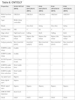
If the power-source voltage drops below 4.5 V, the ACMP will trigger the CNT3/DLY3 to form the “program” pulse initiating the memory writing sequence. Both VDD pins are connected to the source through the Schottky diode and together with the 2.2 µF capacitor to delay power off. Therefore, even if the source voltage drops rapidly to 0, the VDD voltage will slowly decay, leaving enough time for the memory writing sequence to complete (Fig. 3).

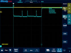
To measure the time required for the program sequence, a simple setup was used. It’s known that the current consumption significantly increases during the erase and write procedure. Thus, the power supply to the IC was connected through a 1-kΩ resistor with oscilloscope probes connected to it.
As can be seen in Figure 4, the program time for both rheostats is 25.28 ms, and the current during the process is about 1 mA. It should be noted that these values depend greatly on the voltage level, room temperature, and other factors. The program time may increase two to three times. So, the power-off delay must be longer than that.
The program procedure starts when VDD drops below 4.5 V, and it should end at no less than 2.5 V (see the datasheet). The 2.2-µF capacitor ensures a long enough power-off delay with room to spare (Fig. 3, again). Note that the capacitor type should be chosen with low leakage.
Also, since the potentiometer is connected between VDD and GND, there will be a constant current flowing through it:
5 V/100 kΩ = 50 µA
That’s an order of magnitude more than the quiescent current of the SLG47004. To reduce overall current consumption, the Wake and Sleep (W&S) timer is used. It’s set to 1:100, meaning that the current will flow through the potentiometer only once in a hundred of clocks of the OSC0. Approximately 0.49-ms wake and 49-ms sleep. As a result, the device's quiescent current described here is close to 3 µA in an off state, making it perfect for battery-operated gadgets.
As previously mentioned, the designed device is equipped with an LED monitor. Two op amps configured as ACMPs are used for this purpose. OPAMP0 senses the LED brake and OPAMP1 senses the LED short circuit. In both cases, it switches off the P-FET and powers down the load (camera/mic). Also, both op amps are enabled only when the switch is on, helping to save the battery in an off state.
This design also is equipped with an internal button to debounce delay (CNT2/DLY2), instead of the typical external RC filter in such cases.
Design Operation: Macrocells
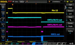
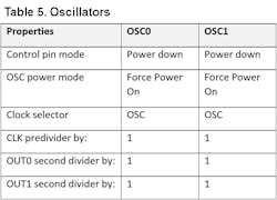
Pin12 is configured as a digital input with Schmitt trigger that has a 100k pull-up resistor. It serves as an input for the pushbutton (Fig. 1, again). Then the signal goes through the 30-ms debounce delay (CNT2/DLY2), triggering the 1.46-ms one shot (CNT1/DLY1). This starts the OSC1 (2.048 MHz), forming a Write Window with a series of pulses to change the state of the potentiometer RH0RH1. See the oscilloscope screenshot in Figure 5.
OSC0 serves as a clock for all counter-delays in this design. Since it has very low power consumption (0.44 µA), it’s set to Force Power On.
As mentioned in the “Schematic Design” section, the SLG47004 has two rheostats—in this project, they’re configured as one digital potentiometer. Its upper and lower pins (Pins 6 and 9) are connected in between ground and Pin 15, which is an output for the W&S timer. The middle tap (Pins 7 and 8) is connected to Latch 1 through a digital input with Schmitt trigger Pin 21.
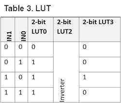
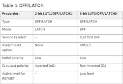
Latch 1 latches the potentiometer state during sleep mode (using an inverted W&S signal), making an appearance as if the potentiometer is constantly connected to VDD but consuming 100X less current. After the latch, the signal goes to a potentiometer’s Up/Down input through a 2.44-ms delay (CNT5/DLY5) needed for the pot to settle in. This signal flips the potentiometer’s count up or down with every next write window. Simultaneously, the signal goes through the filter (filtering a 20-ns spike appearing due to the latch’s lag) to 2-bit LUT3. The LUT controls the output power P-FET (Pins 19 and 20).
The LED monitor consists of OPAMP0 and OPAMP1 and analog inputs Pins 4 and 24. It detects the LED’s short circuit or circuit break, and with the help of 2-bit LUT0, DFF3 shuts down the P-FET if the LED malfunctions.
The Wake and Sleep timer (WS Ctrl) plays an important role in saving energy if the device is battery-operated. Since this project uses analog macrocells that are the most “energy-hungry,” the W&S makes it possible to save energy by powering on those macrocells for a short period of time. The wake-to-sleep ratio is set to 1:100.
The CNT3/DLY3 together with ACMP0L start the pot’s “program sequence” as described in the Schematic Design section (see Fig. 1 and the oscilloscope screenshots in Fig. 3).
It should be noted that the I²C macrocell along with its Pins 10 and 11 are used only to program the chip during production and should not be used during device operation. Pins 10 and 11 should be left unconnected on the PCB.
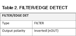
Tables 1 through 11 below provide specifications on the different elements involved in the macrocell’s configuration.


Conclusion
The circuit described in this article functions like a mechanical toggle switch, but uses a micro pushbutton that can be easily integrated into the gadget’s design. The power switch has a memory akin to a mechanical switch, meaning if the user turned it off, it stays off.
In this design, an LED is used as a power indicator. It has fault protection, so if the LED is not glowing for any reason, the load (camera/mic) will also be off, ensuring desired privacy protection. In addition, in an off state, the device has a very low current consumption of approximately 3 µA, which is perfect for most battery-powered devices.
About the Author
Nazar Sliunchenko
Technical Documentation Manager, Renesas Electronics
Nazar Sliunchenko graduated from National University "Lviv Polytechnic" in 2008, studying at the Department of Telecommunications, Radioelectronics & Electronic Engineering. He has more than 15 years of experience in hardware design, including analog and digital devices. Currently, Nazar is managing one of the Technical Documentation departments at Renesas Electronics Corp.
Comment About the Article
To join the conversation, and become an exclusive member of Electronic Design, create an account today!

Leaders relevant to this article: