Design a Deployable SPE Condition-Monitoring Vibration Sensor
Members can download this article in PDF format.
What you'll learn:
- Designing a PODL interface and low-noise power supply for the SPE sensor.
- Choosing the MCU and software architecture.
- Specifying the digital hardware design and a mechanical enclosure.
New single-pair Ethernet (SPE), or 10BASE-T1L, physical-layer standards developed by the IEEE are offering novel connectivity solutions for communicating asset health insights for condition-based monitoring (CbM) applications. SPE provides a shared power and high bandwidth data architecture, where 10-Mb/s data and power are shared on a low cost two-wire cable at over 1,000-meter distances.
Analog Devices designed the industry’s first 10BASE-T1L MAC-PHY (ADIN1110), which is a SPE transceiver with embedded MAC. The ADIN1110 communicates with an embedded microcontroller using a simple SPI bus, reducing both power consumption and firmware development time for the sensor.
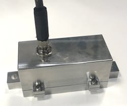
In this article, you will learn how to design a tiny but powerful sensor (Fig. 1).
This article will cover:
- How to design a small, shared data and power communications interface.
- How to design an ultra-low-noise power supply for the sensor.
- Microcontroller and software architecture choices.
- Choosing a suitable MEMS vibration sensor.
- Integrating a digital hardware design and a mechanical enclosure.
- Examples for data-collection UI at your PC.
What is PoDL?
Power and data are distributed on a single twisted pair using an inductor capacitor network (Fig. 2). High-frequency data is coupled to the data lines through series capacitors, which also protect the ADIN1100 10BASE-T1L PHY from dc bus voltages (Fig. 2a).
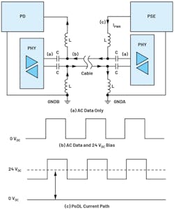
Figure 2 shows a power supply connected at the power-sourcing-equipment (PSE) controller via a coupled inductor connected to a data line. The 24 VDC power biases the ac data bus (Fig. 2b). In Figure 2c, the current path is shown as IPWR between the PSE and powered device (PD), with the power extracted from the line using a coupled inductor at the CbM sensor node.
To protect against incorrect polarity cable installations—for example, a fault where the 24 VDC of the PSE PHY is wired to the 0 VDC of the PD PHY—a bridge rectifier diode is recommended. For EMC robustness, a TVS diode with working voltage greater than 24 VDC is required. Additional EMC components can be used (for example, high-voltage capacitors on signal wires) if the sensor hardware design is larger.
Designing a small shared data and power interface (PoDL) circuit using all of these components can be challenging, but fortunately most vendors have competitively sized solutions for rectifier diodes, TVS diodes, and passive components. Generally, components with ultra-low capacitance must be chosen to minimize signal distortion.
The coupled inductor and capacitor are recommended to have inductance and capacitance values of 220 µH and 220 nF, respectively, but they can be larger in simulation or testing for design margin. A selection of very small size components usable for sensor design are listed in Table 1.

How Do I Design a Small PoDL Circuit?
Figure 2 includes the coupled inductor and series capacitors as the most basic components required for the PoDL operation. Additional components are required for robustness and fault tolerance.
Because the PoDL coupled inductors are non-ideal components, some differential to common-mode conversion will occur. This common-mode noise will degrade signal quality.
Connecting a common-mode choke close to the cable connector helps to mitigate against this non-ideal behavior and protects the design against common-mode noise coming from the cable. The common-mode choke ampacity and dc resistance (DCR) will need to be examined to ensure that they can support adequate power delivery for the sensor.
The coupled inductor rated current needs to meet or exceed the total current requirements for the remotely powered MEMS sensor node. The LPD5030-224MRB is rated to at least 240 mA, greatly exceeding the requirement for a 10BASE-T1L sensor node. Because the rated current requirement is relatively low, the inductor size can be reduced. Table 2 shows that the 4.8- × 4.8-mm LPD5030-224MRB is the smallest component to satisfy the 10BASE-T1L link requirements.

How Do I Check if My PoDL Circuit Will Work?
The IEEE 802.3cg-2019 standard for 10BASE-T1L outlines electrical specifications for a PHY to meet, including voltage levels, timing jitter, power spectral density, return loss, and signal droop (decay). The PoDL circuit affects the communication channels, with return loss and signal decay (or droop) being two significant factors.
Return loss is a measure of signal reflections likely to occur on a network and is caused by impedance mismatches at all locations along a cable link. Return loss, expressed in decibels, is of particular concern for high-data-rate or long-cable-reach (1700 m) communications used in 10BASE-T1L.
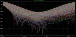
Figure 3 (based on the work of Graber1) shows an LTspice simulation circuit for the single-pair Ethernet 10BASE-T1L standard (10SPE) physical layer or MDI. The simulation circuit includes termination resistance of 100 Ω ±10% for the ADIN1110 or ADIN1100 10BASE-T1L Ethernet PHY/MAC-PHY. Signal coupling capacitance, power coupling inductors, common-mode choke, and other EMC protection components are modeled.
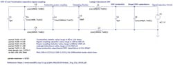
The power coupling inductance is nominally 1000 µH, which accounts for two 220-µH inductors with two windings each (880 µH plus margin). For some components, the recommended component value and tolerance range are added using LTspice Monte Carlo syntax. Figure 4 shows the corresponding Monte Carlo simulation waveform and limit line added using LTspice. The chosen components and tolerances will meet the return-loss mask specification.
How to Design an Ultra-Low-Noise Power Supply
Wired condition-monitoring sensors have stringent noise immunity requirements. For CbM of railway, automation, and heavy industry (for example, pulp and paper processing), vibration-sensor solutions need to output less than 1 mV of noise to avoid triggering a false vibration level at the data acquisition/controller.
Therefore, the power-supply design needs to output very little noise (low output ripple) into the measurement circuit (MEMS signal chain). The power-supply design for the MEMS sensor also must be immune to noise coupled to the shared power and data cable (high PSRR).
Ensuring that a MEMS sensor can detect very small vibrations requires a very-low-noise supply. The ADXL1002 MEMS accelerometer has an output-voltage noise density specification of 25 µg√Hz. During normal operation, the MEMS power supply needs to meet or exceed this specification to avoid degrading sensor performance.
Wired CbM sensors are typically powered from 24 to 30 VDC, which requires a buck converter with high input range and high efficiency to minimize power dissipation and improve sensor long-term reliability. Due to non-ideal capacitive loading, the buck-converter voltage ripple can be tens of millivolts, which isn’t suitable for supplying 3-/5-V MEMS sensors.
Using a common-mode choke or bulk capacitance can reduce the buck output ripple voltage. However, an ultra-low-noise LDO regulator is required at the buck output to ensure that a power supply with microvolts of noise is supplied to the MEMS sensor.
Powering a 10BASE-T1L Sensor Prototype
Figure 5 shows a power-supply design for a digital wired MEMS sensor. The LT8618 is specifically designed for industrial sensors with:
- Wide input range up to 60 V
- Low output current of 100 mA
- Up to 90% efficiency
- Tiny 2- × 2-mm LQFN packages
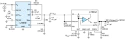
The LT8618 has a 24-VDC input that’s regulated to 3.7 V and then input to the LT3042, which supplies 3.3 V to the MEMS sensor circuitry (Fig. 5, again).
The LT3042 is a high performance ultra-low-noise LDO regulator with:
- Ultra-low rms noise at 0.8 µV rms (10 Hz to 100 kHz)
- Ultra-high PSRR (79 dB at 1 MHz)
- Tiny 3- × 3-mm DFN packages
The article “How to Get the Best Results Using LTspice for EMC Simulation—Part 1”2 details an LTspice simulation circuit and discusses the EMC performance for the LT8618 and LT3042. Figures 19 and 20 from that article present simulation results for where an EMC disturbance is applied at the LT3042 input. This shows that the LT3042 has less than 200 µV of voltage ripple even in the presence of a 1-V p-p EMC disturbance at its input.
Integrating a Digital Hardware Design and Mechanical Enclosure
A steel or aluminum enclosure is used to house a MEMS vibration sensor and provide solid attachment to monitored assets, as well as provide water- and dust-proof capability (IP67). For vibration sensors, the natural frequencies of the enclosure must be greater than that of the applied vibration load measured by the MEMS sensor.
The frequency response plot for the ADXL1002 MEMS is shown in Figure 6. The ADXL1002 3-dB bandwidth is 11 kHz and it has a 21-kHz resonant frequency. A protective enclosure used to house the ADXL1002 needs to have a first natural frequency of 21 kHz or greater in the axis of sensitivity. Similarly, when designing a triaxial sensor, the natural frequencies of the mechanical enclosure must be analyzed across vertical and radial directions.
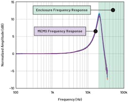
Sensor prototypes are tested on modal shakers, which provide a controlled environment to set vibration test levels and sweep across frequency. The test results of sensor frequency response should closely follow the MEMS sensor information shown in Figure 6.
Modal Analysis
Modal analysis is a commonly used technique to provide a good understanding of the vibration characteristics of enclosures. Modal analysis provides the natural frequencies and normal modes (relative deformation) of a design. Finite element methods (FEMs) using Ansys or similar programs can be used to simulate the modal response of structures, helping to optimize the design and reduce the number of sensor prototype iterations.
Equation 1 is a simplification of the governing equation of modal analysis for a single degree of freedom system. The natural frequency is related to the mass matrix (M) and stiffness matrix (K) of the enclosure design.
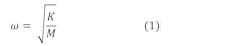
Equation 1 provides a simple intuitive way to evaluate a design. As you reduce the height of the sensor enclosure, the stiffness increases and the mass decreases; therefore, the natural frequency increases. In addition, as you increase the height of enclosure, the stiffness reduces and the mass increases, resulting in a lower natural frequency.
Most designs have multiple degrees of freedom. Some designs have hundreds. Using the FEM provides quick calculations for Equation 1, which would be very time-consuming to do by hand.
When simulating using Ansys modal, both natural frequencies and mode participation factor (MPF) are output by the solver. The MPF is used to determine which natural frequencies are the most important for your design. A relatively high MPF means that a particular frequency may be a problem in your design.
The examples shown in Table 3 illustrate that while a 500-Hz natural frequency is predicted in simulation for the x-axis, the mode is weakly excited and unlikely to be a problem. An 800-Hz strong mode is excited in the enclosure x-axis and will be a problem if the MEMS sensitive axis is oriented in the enclosure x-axis. However, this x-axis strong mode at 800 Hz isn’t of interest if the designer has a MEMS sensor PCB oriented to measure in the enclosure z-axis.

Modal Analysis for a 10BASE-T1L Sensor Prototype
The article “How to Design a Good Vibration Sensor Enclosure Using Modal Analysis”3 provides a detailed overview of modal analysis. While Ansys is an efficient and sophisticated tool to analyze the modal response of structures, an understanding of the underlying equations will help in design. The underlying equations show that enclosure natural frequencies are influenced by both material choice and geometry.
Cylindrical shapes with higher cross-sectional areas are better designed for higher rigidity and natural frequencies across all axes, compared to rectangular shapes. Rectangular shapes offer more options in sensor orientation and equipment attachment, compared to cylindrical shapes. Please refer to the article for examples and simulation results.
The 10BASE-T1L sensor prototype is designed using a triaxial 1-kHz bandwidth MEMS sensor (ADXL357), and the design goal is to create an enclosure that supports greater than 1 kHz. A rectangular enclosure design was created (Fig. 7) and simulated using Ansys.
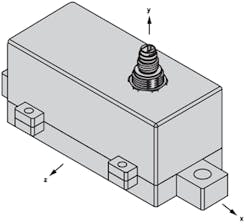
Table 4 shows the simulation results, with natural frequencies and mode participation factors indicating a minimum of 6-kHz bandwidth across all three axes. The design uses M6 lugs on the x-axis surface ends. Using these attachment points will ensure a solid equipment attach and best modal performance.

What Specs Should We Look Out for When Choosing an Accelerometer?
Though no official standard categorizes vibration sensors, they can be assigned into categories using their effective resolution (Fig. 8). It can be clearly seen that MEMS accelerometers cover a small area compared to piezoelectric sensors. MEMS accelerometers have been designed for many application-specific uses such as airbag crash detection, roll-over detection in vehicles, robotic arm positioning, platform stabilization, precision tilt detection, and many more.
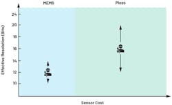
MEMS manufacturers developed sensors good enough to compete with integrated electronic piezoelectric (IEPE) vibration sensors only a few years ago, which means this technology is still in its infancy. As a result, there’s a smaller area of coverage for wired CbM installations, as shown on the left in Figure 8. However, it’s expected to grow in the coming years as more MEMS vendors invest in condition-monitoring vibration-sensor solutions.
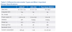
MEMS sensors offer some advantages that are proving disruptive in the world of vibration sensors. For example, most MEMS sensors available on the market have three axes, integrated analog-to-digital converters (ADCs), digital filtering, excellent linearity, low cost, low weight, and very small compared to piezoelectric or IEPE/ICP sensors (Table 5).
While IEPE sensors will continue to be used on the most critical assets, maintenance and facility managers are looking to extract deeper insights from less critical assets in a shift toward extracting better productivity, efficiency, and sustainability—i.e., minimizing unplanned downtime and prolonging the lifetime of assets. Lower-cost and -performance sensors, whether they be MEMS or IEPE, will be used in such scenarios, which raises the question: Is a single-axis IEPE sensor with superior noise and bandwidth performance always a better choice than a MEMS sensor with three axes?
How Do 3-Axis MEMS Sensors Compare to IEPE Vibration Sensors?
Extensive testing has been carried out on the efficacy of triaxial MEMS accelerometers in identifying, with absolute confidence, specific faults that much higher performance single- or even dual-axis IEPE vibration sensors could not detect, as summarized in Table 6.1

Faults like a bent shaft, eccentric rotor, bearing issues, and cocked rotor could not be detected by a single-axis vibration sensor with absolute certainty, unless some efforts were taken to understand specific anomalies prior to mounting. When only a single-axis vibration sensor is available, other CbM sensors, such as motor current or magnetic field, would be required to identify certain faults with more confidence.
A tradeoff exists between a single-axis sensor with superior noise and bandwidth vs. triaxial sensing. These extra axes can alleviate mounting position challenges because all of the vertical, horizontal, and axial vibration will be detected, as well as offer deeper insights into the operation of an asset. According to the results presented in Table 6, most of the faults could not be confidently identified with a single-axis sensor without reorienting and retesting, even if it has superior noise and bandwidth vs. a triaxial MEMS sensor.
What Other Vibration Sensors are Available and How Do They Compare?
So, how do three-axis MEMS sensors fit into the vibration sensor spectrum? Figure 9 shows an overview of the MEMS vibration sensors available today based on their noise vs. bandwidth. IEPE sensors are included for reference and help highlight where exactly MEMS sensors fit onto the vibration sensor spectrum.
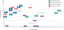
It’s clear that the different types of MEMS sensors naturally form clusters which can be used to assign potential use cases. For example, the lowest-cost sensors (MEMS triaxial) would be used on lower-criticality assets whereas the highest-cost sensors (IEPE) will be employed on the highest-criticality assets.
Single-axis IEPE sensors have been around for decades and cover all areas from low- to high-criticality applications and are widespread in terms of cost and performance (Fig. 9, again). It’s evident that triaxial IEPE sensors have similar performance to triaxial MEMS sensors, but at a much higher cost. For the low-criticality assets cluster, it’s not viable to use triaxial IEPE sensors due to their high cost, but this further highlights the point that triaxial MEMS sensors can compete with some triaxial IEPE sensors in terms of noise and bandwidth.
What Sensor Was Most Suitable for the Deployable SPE Condition-Monitoring Sensor and Why?
The deployable single-pair Ethernet condition-monitoring sensor was designed to house a vibration sensor. However, the system architecture allows for many types of sensors, such as temperature, pressure, sound, position, etc., to be used whether they’re analog or digital output with minimal changes to the microcontroller firmware.
The vibration sensor had to be small, digital out (SPI or 12C) with high levels of integration (amplifiers, ADCs) to meet the size and performance requirements of the SPE condition-monitoring sensor. A three-axis, digital output MEMS accelerometer was chosen based on the specifications shown in Table 5. A low-noise triaxial sensor was chosen instead of a lower-noise, wider-bandwidth, single-axis MEMS sensor to provide more diagnostic insights (three-axis vs. single-axis) and ease mounting challenges associated with single-axis sensors.
The next key consideration is power consumption, and it’s clear to see that the ADXL357 will produce less self-heating effects inside an IP6x module compared to the other sensors. That’s because the ADXL357 doesn’t need an ADC or op amp, reducing the overall solution size and BOM cost. A reduced solution size ensures a small mechanical enclosure and good modal frequency performance, as explained in the section on modal analysis.
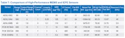
Higher-performance, single-axis, wide-bandwidth (11 to 23 kHz) MEMS sensors, such as the ADXL100x family with up to 14-bit resolution, could be seamlessly integrated. However, this would likely require an external ADC to preserve performance as most low-power microcontrollers only have integrated 12-bit ADCs. But with a suitable microcontroller, oversampling and decimation could be used to increase resolution above 12 bits, meaning a single-axis, analog output MEMS accelerometer could be integrated to the existing system with minimal effort. Please note, if you require better than 13-bit resolution, you must use an analog output MEMS or IEPE sensor (Table 7).
Microcontroller and Software Architecture Choices
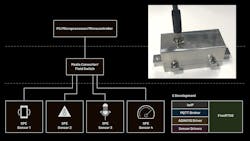
Figure 10 shows simple vibration-sensor-based MQTT architecture and a high-level block diagram for the deployable SPE condition-monitoring sensor interfaced to a PC or Raspberry Pi is depicted in Figure 11.
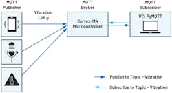

Message Queue Telemetry Transport (MQTT) is a lightweight messaging protocol for the Internet of Things that allows network clients to distribute telemetry data in low-bandwidth environments. It’s considered lightweight due to its messages having a small code footprint. The publish and subscribe messaging transport is ideal for connecting remote devices with a minimal code footprint and network bandwidth.
MQTT is used in a vast array of industries from oil and gas, automotive, telecommunications, and manufacturing. Publishers send messages and subscribers receive messages that they’re interested in. Brokers pass messages from publishers to subscribers. Some MQTT brokers handle millions of concurrently connected MQTT clients, which is one of the attractive features—many sensors could be connected to one SPE device, creating a pipeline of sensor data as shown in Figure 10. Both publishers and subscribers are MQTT clients that can only communicate with the MQTT broker. MQTT clients can be any device such as Arduino, Raspberry Pi, ESP32, or an application like Node-RED or MQTTfx.
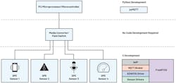
The first four blocks in Figure 11 consist of a sensor, microcontroller, MAC-PHY, and media converter. The sensor is a digital-output triaxial MEMS sensor that can detect vibrations. Any standard low-power microcontroller, such as the MAX78000 or MAX32670, with an SPI interface can be used to read data from the ADXL357. The MAX78000 has the added advantage of providing capability for ultra-low-power edge AI processing, with a built-in convolutional-neural-network (CNN) hardware accelerator.
The measured vibration data is placed into an MQTT topic for transmission to the MAC-PHY, again over SPI. The low-cost Cortex-M4 MCU can be used to read/write to the ADIN1110 MAC-PHY over SPI to enable different modes and configurations, such as PoDL ON or OFF; T1L special, main or subnode; 1 V or 2.4 V.
The ADIN1110 converts MQTT data topics to 10BASE-T1L format and transmits over 300 m of IP67-rated cable with advanced shielding for robustness over 1700 m. The media converter then converts data from 10BASE-T1L to 10BASE-T format so that a PC or Raspberry Pi can interpret the data and subsequently process and display it.
ADIN1110 10BASE-T1L MAC-PHY
The ADIN1110 is a robust, single-port, low-power 10BASE-T1L Ethernet MAC-PHY transceiver targeting industrial applications. With its integrated MAC interface, the ADIN1110 enables direct connectivity with a variety of host controllers via SPI. This SPI communications channel allows for the use of lower-power processors without an integrated MAC, which provides for the lowest overall system-level power consumption.
The ADIN1110 is designed for edge-node sensors and field instruments deployed in building, factory, and process automation. The device operates from a single power-supply rail of 1.8 or 3.3 V. Supporting both 1.0- and 2.4-V amplitude modes of operation and external termination resistors, the ADIN1110 supports use within intrinsically safe environments. The programmable transmit levels, external termination resistors, and independent receive and transmit pins suit the ADIN1110 for intrinsic safety applications.
The vision of Ethernet to the field or edge is to connect all sensors and actuators to a converged IT/OT network. Achieving this vision comes with system engineering challenges, as some of these sensors are limited in power and space. There’s a growing market of low-power and ultra-low-power microcontrollers with significant internal memory capabilities for sensor and actuator applications. But most of these processors have one thing in common: with no integrated Ethernet MAC, they don’t support an MII, RMII, or RGMII media-independent (Ethernet) interface. A traditional PHY can’t be connected to these processors/microcontrollers.
The firmware implementation for the deployable single-pair Ethernet condition-monitoring sensor is shown in Table 8.

Most low-cost Cortex-M4 microcontrollers with sufficient memory would be suitable for this application. The SPE condition-monitoring sensor software architecture can be seen in Figure 12, and it consists of multiple elements with a corresponding block diagram shown in Figure 13.
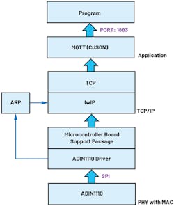
The microcontroller can easily handle the operating system (FreeRTOS) and MQTT libraries, as well as the lightweight IP stack or lwIP. The IwIP is a small independent open-source implementation of the TCP/IP protocol suite designed to reduce RAM usage while still having full-scale TCP. FreeRTOS provides an open-source, very well documented and supported operating system that makes it easy to add new functional blocks of code.
The aim of the lwIP TCP/IP implementation is to provide a full-scale transmission control protocol (TCP) while reducing resource usage, making lwIP ideal for use in embedded systems with tens of kilobytes of free RAM and roughly 40 kB of code ROM. In addition, add-on applications such as MQTT client were used to provide MQTT functionality.
The MQTT block is configured in publish/subscribe mode, providing a streamlined, high-efficiency solution. The ADIN1110 driver needs to communicate with an address resolution protocol (ARP) block before communicating with the lwIP stack to ensure seamless network communications between the microcontroller and ADIN1110.
PyMQTT is a Python-based library extension for integrating an MQTT client into a web application. It’s used to subscribe to the SPE sensor, extract data, and display it in a GUI. Therefore, it effectively acts as a wrapper around the paho-mqtt package to simplify MQTT integration into a Python application.
ADIN2111: Two-Port Ethernet Switch with Integrated 10BASE-T1L PHYs
The ADIN2111 (Fig. 14) adds Ethernet connectivity to every node in a factory/building using long-reach 10BASE-T1L technology, simplifying network management. It supports low-power edge-node designs and interfaces to a wide variety of host controllers via SPI. A two-port switch such as ADIN2111 could be used for daisy-chaining data between constrained edge nodes in a line or ring topology.
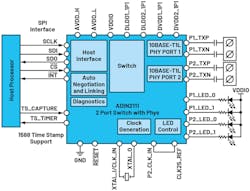
Line and ring topologies are the dominant architecture in industrial deployments. Each device will require two ports for input and output; thus, each device will need a switch and two 10BASE-T1L PHYs as provided by ADIN2111.
The ADIN2111 comes with a suite of diagnostic features and can monitor link quality and detect faults to reduce commissioning time and system downtime. It enables real-time fault detection and fault-location detection with 2% accuracy over 1 km of cable, which helps reduce downtime and commissioning time. The device enables networks of sensors, actuators, and controllers to be connected in a line or ring topology while utilizing existing deployed single twisted-pair cabling infrastructure.
Data Acquisition and GUI
Vibration data can be visualized in the time and frequency domain using the Python-based GUI (Fig. 15). The Python GUI is an executable; no code development is required unless you want to modify it.
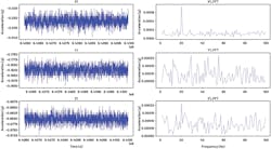
To verify the performance of the SPE sensor system, a series of tests were carried out. Imbalance load tests are a reliable method to test the performance of a vibration sensor, since the time- and frequency-domain signatures are easily recognized.
Figure 16 shows the time-domain data on the left and frequency-domain data on the right. On the y and z axes, there’s a clear sinusoidal signal correlating to the vibrations measured from the imbalanced load at the motor’s rpm or fundamental speed. This is because the y and z axes were positioned to measure the largest vibration responses from the imbalanced motor.
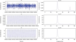
Though the x axis does measure some repetitive data, it’s not sinusoidal and an order of magnitude or more lower in amplitude than the y and z axes. However, on the frequency-domain plots, the x-axis clearly shows an imbalance signature, as do the y and z, but on a much higher magnitude.
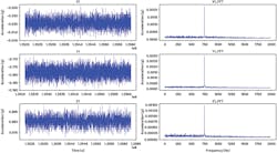
To investigate the noise performance of the system, another test was used whereby a tone generator was placed on the same baseplate as the SPE sensor (Fig. 17). Vibrations are imperceptible to the human hand, but the ADXL357 coupled with the 10BASE-T1L communications pipeline can reliably detect anomalies on all three axes.
References
1. Steffen Graber. “10 Mb/s Single Twisted Pair Ethernet, 10BASE-T1L MDI Return Loss.” IEEE, May 2018.
2. Richard Anslow and Sylvain Le Bras. “How to Get the Best Results Using LTspice for EMC Simulation—Part 1.” Analog Devices, Inc., November 2021.
3. Richard Anslow. “How to Design a Good Vibration Sensor Enclosure Using Modal Analysis.” Analog Devices, Inc., February 2022.
About the Author
Richard Anslow
System Applications Engineer, Analog Devices
Richard Anslow is a systems applications engineer with the Connected Motion and Robotics Team within the Automation and Energy business unit at Analog Devices. His areas of expertise are condition-based monitoring and industrial communication design. He received his B.Eng. and M.Eng. degrees from the University of Limerick, Limerick, Ireland.
Comment About the Article
To join the conversation, and become an exclusive member of Electronic Design, create an account today!

Leaders relevant to this article: