Solid-State Photorelay Tackles High Frequencies, ATE Signal Switching

The most basic on/off relay-switching function, conventionally designated as 1-Form A (Normally Open - NO), can be satisfied by an electromechanical relay (EMR) or a solid-state relay (SSR), but that’s only part of the relay story. For high-speed signals, especially those in automatic test equipment (ATE), parameters such as parasitic capacitance and inductance, along with associated insertion loss, are also critical.
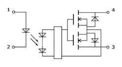
Addressing this situation, Toshiba Electronics introduced the TLP3475W photorelay (often called an SSR), which reduces those contributors to insertion loss. It targets the high-frequency signals associated with semiconductor testing applications such as high-speed memory testers, high-speed logic testers, or probe cards (Fig. 1).
With its optimized package design, this photorelay provides functionality up to 20 GHz (typical)—a 50% improvement in performance over the existing predecessor TLP3475S photorelay—and competes with reed relays that are also compact, reliable, and support wideband operation.
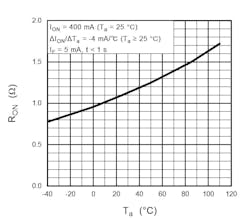
Maximum off-state output-terminal voltage is at least 60 V, while isolation voltage (BVs) exceeds 300 V rms. Output capacitance (COFF) is less than 20 pF, contributing to switching times in the region of 2 ms. Operating temperature range is −40 to +110°C, suiting it for industrial applications as well as high-speed semiconductor testing, where modest ambient temperatures are countered by high duty cycles and load factors that may cause an increase in internal heat (Fig. 2).
The TLP3475W comes in a WSON4 package measuring just 1.45 × 2.0 × 0.8 mm, making it one of the smallest photorelays currently available. This size is 40% smaller than Toshiba's already established ultra-compact S-VSON4T package. Thus, it’s a good fit for the dense multi-channel designs where multiple devices are used on a single card, often the situation in ATE systems.
Details are in the photorelay’s 11-page datasheet. There’s also a 14-page application note, “Points for photorelays in high frequency circuit applications,” which provides additional perspectives including models of parasitic inductance and capacitance in on/off states, along with discussion of S-parameters and insertion loss.
About the Author

Bill Schweber
Contributing Editor
Bill Schweber is an electronics engineer who has written three textbooks on electronic communications systems, as well as hundreds of technical articles, opinion columns, and product features. In past roles, he worked as a technical website manager for multiple topic-specific sites for EE Times, as well as both the Executive Editor and Analog Editor at EDN.
At Analog Devices Inc., Bill was in marketing communications (public relations). As a result, he has been on both sides of the technical PR function, presenting company products, stories, and messages to the media and also as the recipient of these.
Prior to the MarCom role at Analog, Bill was associate editor of their respected technical journal and worked in their product marketing and applications engineering groups. Before those roles, he was at Instron Corp., doing hands-on analog- and power-circuit design and systems integration for materials-testing machine controls.
Bill has an MSEE (Univ. of Mass) and BSEE (Columbia Univ.), is a Registered Professional Engineer, and holds an Advanced Class amateur radio license. He has also planned, written, and presented online courses on a variety of engineering topics, including MOSFET basics, ADC selection, and driving LEDs.
Comment About the Article
To join the conversation, and become an exclusive member of Electronic Design, create an account today!

Leaders relevant to this article: