Understanding Electrocardiograph (ECG) Measurements
A description of the electronics in an electrocardiograph and what signals they measure to produce the “leads” on an ECG strip chart or video display.
Table Of Contents
- What An ECG Does
- Don’t Confuse Wire Leads With Display “Leads”
- What Voltages Are Sensed
- Lead-Off Detection
- Low Voltages And Sources Of Interference
- References
What An ECG Does
An ECG detects and displays the electrical pulses, with amplitudes of a few millivolts, that are associated with heartbeats. They can be picked up at many points on the body, but decades of medical tradition have standardized the accepted locations of those points. By looking at the differential signals across different sets of locations, a physician gains the insights to assess heart functionality from multiple viewing angles.
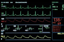
Reading those results is something of an art, because, by practicality (originally) and tradition (today, even though the possibility of digital signal processing now exists), ECG signals are simply displayed as separate time-domain traces on the ECG display or printout. Each of those traces represents a differential voltage between two specific electrodes or a differential voltage between one electrode and the average voltage from several others (see the figure).
Don’t Confuse Wire Leads With Display “Leads”
By medical tradition, the channels are commonly called leads, which creates some ambiguity when the number of medical leads does not correspond to the number of input wires attached to the patient. The maximum number of leads displayed on an ECG is usually 12, which means that a “12-lead” ECG generally would have 10 electrodes. Nine ECG contacts monitor heart signals across different parts of the body. The tenth, called the “right leg” (RL) electrode, is electrically driven to reduce the common-mode voltage. The other nine input electrodes are the left arm (LA), right arm (RA), left leg (LL), and six precordial (chest) electrodes, designated V1 through V6.
What Voltages Are Sensed
When electrodes are grouped, their voltage is averaged. Thus, RA, LA, and LL are averaged and become one side of differential pairs designated V1 to V6. That accounts for six leads on the display. Three other display leads represent the differential voltage between RA, LA, and LL and the average of the other two electrodes. The remaining three display leads on a “12-lead” ECG readout represent combinations of RA, LA, and LL, measured differentially.
In addition to the body-generated signals, a higher-end ECG may display other input signals, such as the “pace” signal, generated by a pacemaker, if the patient has one. It is characterized by short duration (in the range of tens of microseconds to a few milliseconds, and amplitude ranging from a few millivolts to 1 V). That’s a much higher voltage than the differential signal from the heart, and one of the challenges for engineers designing a new ECG is keeping the pace signal from interacting with the other channels.
Lead-Off Detection
Another common non-heart signal is called lead-off. As the name suggests, it represents a fault situation. To detect lead-off, the ECG monitors the impedance between each of the differential-sensing electrodes and the lead-off electrode. Sometimes, this impedance measurement provides an input for measurements of respiration rate. This is detected by changes in thoracic impedance as the chest rises and falls.
Low Voltages And Sources Of Interference
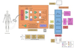
The ECG electrodes detect very small voltages, so a key element in the signal chain is the analog front end (AFE), consisting of several amplifiers and, in modern digital ECGs, the analog-to-digital converter (ADC). The heartbeat signals of interest are in the millivolt range and cover a frequency range from 0.05 to 100 Hz, which are a challenge to measure in the presence of higher-frequency ambient noise from the hospital staff’s and visitors’ cell phones, along with computer clocks and switching power supplies.
Then there are the higher-amplitude pace signals, lead-off signals, and signals from the impulses driving other muscles besides the heart. Besides that, the various differential inputs can be riding on common-mode voltages or dc offsets of hundreds of millivolts. Defibrillation is another noise source that requires input circuit protection and fast recovery time.
Previously, these complications led to large investments in engineering design hours and bench testing whenever a new ECG was devised. Today, the trend is for semiconductor companies to create optimized AFEs that can be used in a range of products, leaving the specialization to the design of back-end signal processing and display functionality.
References
About the Author

Don Tuite
Don Tuite (retired) writes about Analog and Power issues for Electronic Design’s magazine and website. He has a BSEE and an M.S in Technical Communication, and has worked for companies in aerospace, broadcasting, test equipment, semiconductors, publishing, and media relations, focusing on developing insights that link technology, business, and communications. Don is also a ham radio operator (NR7X), private pilot, and motorcycle rider, and he’s not half bad on the 5-string banjo.
Comment About the Article
To join the conversation, and become an exclusive member of Electronic Design, create an account today!

Leaders relevant to this article: