Let’s say you chose a particular microcontroller for its 12-bit analog-to-digital converter (ADC). You built up your system, and although the ADC gives you 12 bits of resolution, the lower couple of bits are frustrating and “unreliable,” to put it nicely. Fortunately, you can reduce or remove this noise with one of two different types of software filters.
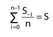
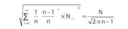
Every sample from an ADC is a combination of signal (S) and noise (N). The goal is to reduce the noise without impacting the signal. Fortunately, noise is incoherent and adds in a root sum of squares (RSS) fashion. This can be exploited with a simple averaging of several samples. Equations 1 and 2 show the result on both the signal and the noise for “n” samples averaged together:
Equation 1:
Equation 2:
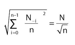
It is apparent that the signal is not affected while the noise sees some reduction. The reduction in noise is inversely proportional to the square root of the number of samples. Each time the number of averaged samples doubles, the noise is reduced 1/√2 or 3 dB per octave. (3 dB is a more technical way for saying √2 and octave for a factor of two.)
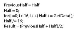
Filters that use a finite number of samples with no feedback are called finite impulse response (FIR) filters. They are also called “boxcar” filters because the response to an impulse is a rectangular output “n” samples wide. The following code shows how to implement this filter in software:
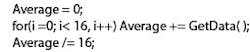
In this particular routine, 16 values received from GetData() are accumulated and then divided by 16. This filter is easy to implement. But if the filtered value is to be updated after each sample, “n” of the previous samples needed to be saved.
Many times, however, “n” unique samples are filtered, resulting in a single filtered value. This is known as decimation. (A 16-kilosample-per-second (ksps) data stream that is filtered with a /16 decimation filter results in a 1-ksps output stream.) With a decimation filter, there is no need to store previous samples.
A Filter with Feedback
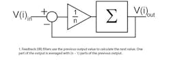
Another type of filter uses the previous output value to calculate the next value. With this type of filter, one part of the input is averaged with (n – 1) parts of the previous output (equation 3):

Note that the equation has been altered to allow for simpler computing. This new form only requires one subtraction, one division, and one addition (Fig1).
Each input is attenuated by n, and each time the output is fed back, it is attenuated by (n – 1)/n, again exploiting the incoherent nature of the noise. Equations 4 and 5 show the result the filter has on the signal and the noise:
Equation 4:

Equation 5:
As with the first filter, the signal is not affected. But the reduction in the noise has now increased nearly √2 times that of the old filter. The noise reduction is still 3 dB/octave. This type of filter is known as an infinite impulse response (IIR) filter. The term infinite is used because the effect each input has on the output theoretically never completely diminishes.
As a bit of history, Alexander Graham Bell observed that sound levels are only attenuated and never completely disappear. He stated that everything ever said was still floating around and that he would attempt to design a device that would recover the actual voice of Jesus preaching his sermon on the mount.
The code below shows how to implement this filter in software:
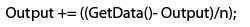
The output will have to be initialized before use. Although easy to implement, when used for decimation, the filter will have to be operated once for each input sample, not just once for each decimated output as with the FIR filter. Without decimation, the filter requires only one value to be stored instead of “n” samples for the FIR filter.
Frequency Plots for Both Filters
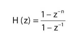
It is apparent that for the same amount of attenuation, the second filter has a greater amount of noise rejection. A frequency response (Bode) plot will show why. For the FIR filter, its z transform, magnitude, and roll-off frequency (i.e., the point at which the amplitude falls below 3dB) are (Equations 6, 7, and 8):
Equation 6:
Equation 7:
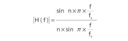
Equation 8:
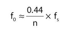
As a result, averaging 16 samples at a 10-ksps sample rate results in a low-pass filter with a rolloff frequency of 275 Hz (0.44 · π ·10 ksps/16). For the IIF filter, the z transform, the filters magnitude, and the roll-off frequency are (Equations 9, 10, and 11):
Equation 9:
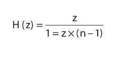
Equation 10:
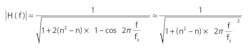
Equation 11:
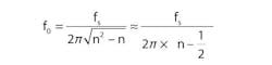
Averaging one part of the input with 15 parts of the old output for a 10-ksps sample rate results in a low-pass filter with a roll-off frequency of 103 Hz (10 ksps/(2π ·15.5)), yielding a significantly lower roll-off point for the IIR filter. The Bode plot for each filter confirms this (Fig.2).
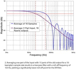
Note that although the IIR filter reduced more noise, it does so by significantly reducing the signal bandwidth. There are a few rules of thumb to follow. First, if signal bandwidth is an issue, then use the FIR filter. Next, if the data is to be decimated, the FIR filter requires fewer calculations. Finally, if the data is not decimated and you lack RAM, use the IIR filter. It only requires storage of the result while the FIR filter requires data storage for each of the previous “n” samples.
If you look closely at Figure 2, I added the plot of the frequency response for an average of 32 samples. Note that it closely follows the IIR filter’s response curve and has roughly the same noise reduction. Below is the code that decimates the output by 16 while still allowing 32 samples to be averaged:
Now you have two different filters to add to your box of tools that you can pull out when noise reduction is needed.
About the Author
Dave Van Ess
Engineer
Dave Van Ess is an application engineer, MTS, with Cypress Semiconductor. He has a BSEE from the University of Calif., Berkeley.
Comment About the Article
To join the conversation, and become an exclusive member of Electronic Design, create an account today!

Leaders relevant to this article: