DAC at 16 bits
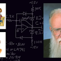
Back 40 years ago, I decided I could design and produce a DAC—a digital-to-analog converter. But I was not going to fool around at 8 or 10 or 12 bits. I was going to design my first DAC at 16 bits (see the figure). At Philbrick we had a customer for a DAC at 13 bits plus sign, and I figured I could easily do that. So, I’d start at 16 and then back up.
The second bit was easy to design with a 10-kΩ high-stability (low-tempco) wire-wound resistor with a 20-Ω trim resistor in series, fed to the emitter of a PNP that fed the current to some more (well-matched, high-beta) PNPs, which were driven nicely by the sign bit. The second layer of transistors steered the current either to an inverting op amp (sigma’) or to the main summing point (sigma) or to ground (OFF).
The reference bit was the same as the second bit and was servoed to a precision, very stable, 1.00-mA current-reference from a 6.200k wire-wound resistor from a stable 6.200-V reference from some 1N825s, etc. Details later.
The most significant bit (MSB) was the same as Bit 2, but with 5.00k and a 10-Ω trim, and it had two emitters in parallel. Bit 3 was the same but with 20k and 60-Ω trim and one emitter, etc. It’s true that the VBE for Bit 3 was ~18 mV off from the earlier bits, but this causes barely 0.7 ppm/°C of degradation.
These resistors’ mismatches could have hurt the gain, but we specified that each set of them was wound with wire from the same spool. The feedback resistors (2.5k) were “Type HS” for fast settling.
We bought a lot of high-beta PNP transistors in those days, so we just graded them into 1/2-dB bins for beta and 1/2-mV for VBE match. We put nicely matched PNPs into blocks of eight wide and groups for high accuracy, all potted nicely into epoxy blocks to be within much less than 1/20°C. It’s true that we had to trim and pad a lot of the resistors to get everything matched well, but what kind of work would you do to make a product to earn $800 in 1970 dollars?
Kicking The Tires
The customer plugged in our first demo and turned on the +5 V dc, the –15 V, and the +15 V, and he reached for the switch for the –60 V dc. But the DAC was already running nicely. It didn’t need any –60 V. What the HEY? The customer was greatly impressed with our DAC’s improved stability and accuracy. It ran cool and efficiently.
We also included a de-glitcher (not shown) to disconnect the main amplifier while the bits were changing. After the bits had settled, the switch (~3N128) turned back on to let the output settle to the new level. This deglitcher ran at 4 MHz, and the customer loved it. This old machine is described on page 12 of the “New Lightning Empiricist” of 1971.
When I was leaving Philbrick in 1976, I found this first DAC, and it was still holding full 16-bit linearity. So I did know something about designing DACs. Good transistors are good transistors. Good resistors are good resistors. These days I’m using some nice slow 16-bit DACs, with a whole lot less effort. But I sure had a lot fun back in 1970.
Comments invited! Beast rgrds. [email protected] —or:
R.A. Pease, 682 Miramar Avenue
San Francisco, CA 94112-1232
About the Author
Bob Pease
Bob obtained a BSEE from MIT in 1961 and was a staff scientist at National Semiconductor Corp., Santa Clara, CA, for many years. He was a well known and long time contributing editor to Electronic Design.
We also have a number of PDF eBooks by Bob that members can download from the Electronic Design Members Library.
Voice Your Opinion!
To join the conversation, and become an exclusive member of Electronic Design, create an account today!

Leaders relevant to this article: