What’s All This Solenoid Driver Stuff, Anyhow?
Download this article in .PDF format
When I showed Bob Pease one of the many solenoid driver circuits available on the Web, he scoffed. “That’s not the way to do it!” he exclaimed. He wrote me:
“Was there a READER who wanted to know how to drive a solenoid better than that old 1996 Design Idea?1 We could show HIM.”
I went to see Bob. He always kept some paper that had been through the workgroup printer but still had one blank side. He grabbed a sheet and whipped up a circuit in no time (Fig. 1a). The beauty of this circuit is that it will hit the solenoid with a higher voltage to pull it in fast, but then lower the voltage and current goes through it so the solenoid does not heat up too much. Bob wrote me a description of the circuit:
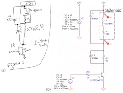
“Driving a relay or solenoid may require a considerable amount of voltage and current to make it ‘Pull In.’ However, to make it ‘Hold In’ may take a lot less current, so you can save some power. The circuit in Figure 1 can easily pull a relay to full voltage for several msec, and then after a suitable time-constant, the current drops off to a ‘Hold-in’ value. Of course, the R and C values must be designed for the coil that is being driven. The R1 should be about 80% of the coil’s dc resistance, and must take into account the tolerance of the supply voltage, if any. For sinking large currents as high as 1 amp, a moderate-sized MOSFET may be suitable, as shown. For smaller currents, a mid-size NPN such as a 2N3904 or PN2222 with 1k to drive its base may be fine. This circuit requires considerably less circuitry than previous designs.”
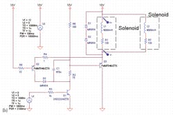
There are a lot of manager types and salespeople and just general citizenry who did not realize how brilliant Bob Pease was. He didn’t wear suits and talk down to people. He was not math-crazy, and certainly not computer crazy. He had a scruffy beard and even scruffier schematics. So I am going to redraw Bob’s schematic to ensure you understand its beauty (Fig. 1b).
Related Articles
- What's All This RIP (Rest In Pease) Stuff, Anyhow?
- What's All This Spicey Stuff, Anyhow?
- What's All This Last Column Stuff, Anyhow?
One thing Bob and I agreed on was that high-impedance circuits can be a pain in the butt. If you have 10-MΩ resistances, a little dirt on the circuit board or a humid day can change the performance of the design. So, Bob’s circuit does not try to put an RC time constant into the gate of a MOSFET.
Instead, he uses a plain old transistor as the pass element. It’s rugged and dirt-cheap. He does not use it in linear mode, like if you had put an RC in the gate of a FET. The transistor turns on hard and fast and, hence, should never burn up due to a slow transition from on to off, or vice versa. Driving an inductive load is tough enough, never mind trying to throttle pass current to tailor the operation of the device. Bob wrote me:
“For a driver for a 1-amp solenoid, which could be a 12Ω solenoid with 8.2Ω 2W resistor in series with it, the cap would need to be about as big as 4700µF. That sounds awful BIG, but the Digi-Key catalog lists this as available for 62 cents in 100s. Barely 1" x 0.5" diameter. I’m going to build this soon. (I gotta go over to Halted2 and buy a couple solenoids...) For driving a 0.1-amp relay or solenoid, 470µF should be big enough, at a cheaper price and cozier size. A 2N3904 or PN2222 should drive that OK. NOTE: 62 cents ain’t quite CHEAP, but I am sure it is cheaper than the ‘L272’ [a Thompson CSF part used in a 1996 Design Idea mislabeled as an LM272].”
The capacitor initially has zero volts across it. Voltage does not change instantly across a capacitor. So when the transistor turns on, all the current passes through the capacitor and you get nearly the full 12 V across the solenoid. You size the capacitor big enough to ensure that you can pull in the solenoid. Once the solenoid is engaged, you can keep it engaged with a lower hold-current.
Bob recommended that you size the series resistor at about 80% of the dc resistance of the solenoid. Once the transistor turns on, then, the big capacitor charges up and the voltage across it builds up. The internal equivalent series resistance of the solenoid and that external resistor you added determine the end voltage.
If the external resistor were 100% of the solenoid dc resistance, the end voltage would be 6 V. Half of the power rail voltage would be across the solenoid and half across the external resistor. The dc current and voltage across the external resistor proivide a nominal power dissipation. You should use a resistor that’s physically big enough to dissipate the power, with a safety factor of 4 or better.
Turning on the solenoid is just half the job. When you turn it off, remember that current does not change instantly through an inductor. So the solenoid will keep driving current, but it has no place to go. The timing capacitor cannot serve as a snubber here, since it is no longer connected to ground. So rather than count on the capacitor to keep the voltages low, Bob did the standard thing with inductive loads. He put a diode clamp across it. He used a big diode.
The 1N4001 is good for 50 V and 1 A. Now when the transistor opens, the voltage starts to fly up at the collector, but the diode limits the voltage to 12.6, a diode drop above the power rail. But remember that voltage cannot change across the capacitor instantaneously. So if the capacitor had 4 V across it in the dc on state, that 4 V will still be there the moment after the solenoid opens.
I pointed out that if you rapidly cycled the circuit on and off, you would not be whacking the solenoid with an initial 12-V spike. All you would get was the 8 V—the hold-in voltage. When I expressed my concern to Bob, he brought up a related issue. You get the same problem when the power rail drops out momentarily.
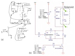
Bob smiled and whipped up another sketch (Fig. 2). You can cycle this solenoid on and off as often as you wish. Pease put in another transistor to ensure that the capacitor is discharged immediately when the solenoid turns off. He wrote me:
“The Figure 1 circuit still has a weakness in common with the older 1996 circuit: If the power bus loses power briefly, or if the command drops out briefly, the coil will get discharged, but the capacitor may not; and the circuit may then refuse to re-start. The capacitor may stay charged up and refuse to provide full voltage to bring the coil to the needed Pull-In level. Figure 2 shows an improvement: If power is lost, the coil discharges its current through two rectifiers. The voltage there causes Q2 to discharge the big capacitor, so when a valid start command is then given, the capacitor will start out at low voltage and push full current into the relay [or solenoid] for several milliseconds.”
Note the symbol Pease used for the pass transistor in Figure 2a. He drew it like an insulated gate bipolar transistor (IGBT). But if it were, it wouldn’t need a series resistor in the gate. Bob’s point was that you can use a NPN, an N-channel FET, or an IGBT, depending on the voltage and current of the solenoid.
The pass transistor applies voltage to the solenoid and the series RC. The circuit turns on the solenoid in the exact same way as Figure 1. The difference is that when this solenoid turns off, the current in the solenoid is routed through two 1N4001 diodes. But these two diodes also have a base-emitter junction and two 22-Ω resistors in parallel.
This means that anytime the voltage across the two 1N4001 diodes gets over a single diode-drop, the PNP reset transistor turns on. When it does, it quickly dissipates any voltage in the capacitor. Now the capacitor has zero volts across it and is almost instantly ready for the next turn-on event.
To get the circuit to demonstrate the principles, I adjusted the values in my schematic so you can use Spice to play with the circuit (Fig. 2b).
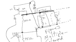
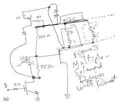
Bob was so delighted when I asked about fast cycling of the circuit, he went on to show me a third circuit you can use with multiple solenoids (Fig. 3).
He wrote me:
“A further refinement as in Figure 3 will permit this basic circuit to drive 1 or 2 or more coils, and still give a safe re-start. Yet it is not necessary to measure the ohms of each coil. A simple PNP follower can drive light or heavy loads. A large capacitor is not required.”
The trick here is to use yet another transistor to isolate the solenoid from the timing components. This third transistor is a voltage follower of the RC waveform that the previous circuits imposed directly on the solenoid. In this multiple load circuit, there is a discrete external 100-Ω resistor substituted for the equivalent series resistance of the solenoid.
Now the parallel RC performs the same turn-on function. The voltage appearing at the base of the voltage follower goes to nearly ground when the circuit turns on. But soon the capacitor charges up and you end up with a dc voltage set by the 100/75-Ω divider: about 5 V. That means the voltage across the solenoid is 7 V, less a diode drop for the base emitter of the voltage follower transistor, about 6.4 V.
The reset part of the multiple solenoid circuit operates pretty much the same as in Figure 2. When the control transistor opens, the base of the voltage follower transistor flies up toward the power supply voltage, since the inductive current of the solenoid has nowhere to go. When the emitter of the follower gets a diode drop above the 12-V rail, the reset transistor starts to conduct. As current is delivered from the solenoid, the two 1N4001 diodes provide a hard-clamp to the voltage excursion. The solenoid voltage flies back long enough to ensure that the reset transistor has had time to discharge the capacitor.
If you immediately hit the circuit with another turn-on event, it will act just like it had been sitting there for an hour. Best of all, the “pull-in then hold” action is independent of how many solenoids you are driving. Just make sure the voltage follower transistor can handle the total solenoid current without overheating. That transistor need not be rated at more than 20 or 30 V, since the clamp circuit will limit the voltage across it to less than 14 V.
Spice Simulations
I insisted on redrawing Pease’s scribbled schematics for a good reason. Drafting is a language, and clear drafting is better than sloppy drafting since it is easier to understand. The flow from left to right and top to bottom tells you something. The placement and sizing of components tells you even more.
So one niggle I had with Bob was his refusal to do CAD schematics. The other was his avoidance of Spice. Once we are 70 years old, let’s hope we all get as brilliant as Bob in our little specialties. But when you are starting out, things are not self-evident. Experience is a mean teacher. It gives you the test first and the lesson afterward. So unlike Bob, I think Spice is great as long as you don’t become overdependent on it.
After fiddling with Spice for a couple days to do this simple task, I can understand Bob’s contempt for it. Once I remembered how to operate OrCAD 9.2 and PSpice, the simulation itself really wasn’t that relevant. Remember that solenoids and relays are non-linear devices. Their inductance depends on whether the ferrous plunger is pulled in or not. I found no Spice models for a solenoid online, although there were 86-page papers full of math trying to describe their non-linear behavior.3
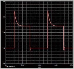
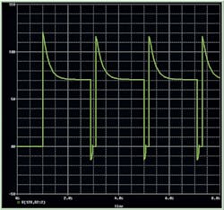
The voltage waveforms for Figure 1b look just dandy. Observe how the solenoid voltage is initially nearly 12 V, then sags down to that dc final voltage of 6 V or so (Fig. 4). When you turn off the control transistor, the solenoid voltage collapses and then reverses by a diode drop as the inductive kick flies back, but the capacitor voltage has to slowly discharge through the 82-Ω resistor that is in parallel with it.
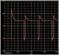
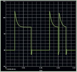
But if you cycle the solenoid very fast, you can see how the solenoid is not hit with that full initial pulse of 12 V, since the capacitor is not fully discharging (Fig. 5).
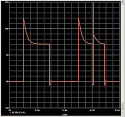
Similarly, when the power rail drops out momentarily, the voltage across the solenoid is reduced when the rail recovers, since the capacitor has not fully discharged (Fig. 6).
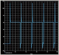
When you Spice the circuit of Figure 2b, you can see the solenoid now gets a full pulse, even for rapid operation (Fig. 7).
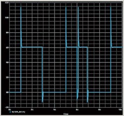
This is because the capacitor voltage is being rapidly discharged by the action of the reset transistor. Equally satisfying, the solenoid gets a full pulse after the power rail drops out momentarily (Fig. 8).
The multiple solenoid circuit is similar to the reset circuit. When operated rapidly, the reset circuit discharges the capacitor to allow rapid operation (Fig. 9).
The same happens when the power rail drops out (Fig. 10). The circuit timing is independent of load since the load is not part of the timing circuit.
Do bear in mind that the load for all these circuits has to be inductive, so the flyback action can turn on the reset transistor and short out the capacitor. Also bear in mind that one reason Bob loved analog was that there are many different ways to get good results. This is evident by all the circuits you can find online to drive solenoids and relays.
I hope I have not belabored the function of this circuit. If you take time to really understand it, you can learn a whole lot of analog electronic principles. Pease would never get upset if you asked how to do something like drive a solenoid. But he would get peeved if you asked “But I have 5-V solenoids. What parts should I use?”
Both he and I expect you to understand the principles of circuits so you can adapt and apply them to your specific application. If all you want is specific component values for a specific application, then you are not an engineer and you are not a technician. You are a purchasing agent and should go bother other purchasing agents.
The CAD files can be downloaded here.
References
1. Barnett, TG “Simple solenoid driver reduces power and cost,” EDN, July 18, 1996, www.ednmag.com/archives/1996/071896/15di4.htm
2. HSC Electronics, www.halted.com/
3. Knight, David W., “An introduction to the art of Solenoid Inductance Calculation With emphasis on radio-frequency applications,” January 2013, www.g3ynh.info/zdocs/magnetics/Solenoids.pdf
About the Author

Paul Rako
Creative Director
Paul Rako is a creative director for Rako Studios. After attending GMI (now Kettering University) and the University of Michigan, he worked as an auto engineer in Detroit. He moved to Silicon Valley to start an engineering consulting company. After his share of startups and contract work, he became an apps engineer at National Semiconductor and a marketing maven at Analog Devices and Atmel. He also had a five-year stint at EDN magazine on the analog beat. His interests include politics, philosophy, motorcycles, and making music and videos. He has six Harley Sportsters, a studio full of musical instruments, a complete laboratory, and a video set at Tranquility Base, his home office in Sun City Center Florida.
Comment About the Article
To join the conversation, and become an exclusive member of Electronic Design, create an account today!

Leaders relevant to this article: