PLL Provides Ratiometric Capacitive Touch Switch For Appliances

This article is part of the Ideas for Design Series: Vol. 3, No. 1
Capacitive-based touch-sensor switches are gaining popularity for appliance, automotive, and industrial applications for many reasons. They’re aesthetically appealing, flexible, easy to manufacture, and easy to use. They avoid the need for buttons, sliders, and other parts needed in mechanical switches. They’re also durable, since they don’t have any moving parts.
This file type includes high resolution graphics and schematics when applicable.
Further, the absence of holes and other openings lowers the manufacturing cost. Surface contaminants and moisture have no effect on the quality of the switches. The front surface can be back-lit to indicate the switch status. And, the copper pads of the printed-circuit board (PCB) can be made to function as touch sensing plates.
Related Articles
- Efficiently Reduce High Supply Voltages To Accurate Low Voltage
- Ten-Cent Charge Pump Provides LCD Bias
- Simple Circuit Shuts Off System When Supply Voltage Is Low
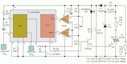
The circuit in the figure uses two identical metal plates or copper pads on one side of a double-sided PCB as the sensing pads (SPOn and SPOff). Sensing capacitors COn and COff are formed by placing these sensing pads behind a thin, decorative overlaying cover film or plate of the switch. The overlay isolates the user from the mains voltage. Components C4, R9, Z1, D1, and C3 form a compact and low-cost transformerless power supply.
The capacitors act as the timing components of the voltage controlled oscillator (VCO) of a commonly used and inexpensive CMOS phase-locked loop (PLL) (CD4046). ON period TOn and OFF period TOff of the square wave at the output of the VCO are determined by the values of the sense capacitors COn and COff, respectively. Integrator R4C1 develops dc voltage Vdc proportional to the duty cycle (η) of the square-wave output:
Vdc = duty cycle × amplitude of the square wave
where:
η = duty cycle = TOn/(TOn +TOff)
and:
amplitude of the square wave = 12 V
Since the sensing pads are identical, the capacitors have equal values when the sensing pads are not touched. Hence, TOn =TOff, duty cycle = 0.5, and Vdc = 6 V. The voltage divider formed by R6, P1, and R7 provides reference voltages VRef-hi and VRef-lo to voltage comparators U2-a and U2-b.
When the sensing pad (SPOn) used for switching the appliance on is touched, the user’s finger capacitance will be added to the value of COn. This increases the values of TOn, the duty cycle, and the integrator output. Preset potentiometer P1 is adjusted so:
VRef-hi = (Vdc + Vdc-on)/2
where Vdc and Vdc-on are the integrator outputs when SPOn is untouched and touched respectively.
Thus, when SPOn is touched, the integrator output exceeds VRef-hi, and the output of comparator U2-a output goes high, setting the set-reset flip-flop, which is the phase comparator (PC-2) of the PLL IC.
Similarly, when sensing pad SPoff used for switching the appliance off is touched, the user’s finger capacitance will be added to the value of COff. This increases the value of TOff and decreases the values of duty cycle and the integrator output.
As R6 = R7, the reference voltage VRef-lo tracks VRef-hi such that:
(VRef-hi - Vdc) = (Vdc - VRef-lo)
Hence, when SPOff is touched, the integrator output falls below VRef-lo, and the output of comparator U2-b output goes high and resets the set-reset flip-flop of the PLL IC. A high level on the flip-flop output drives triac T2 to switch on the electrical appliance connected to it. A low level at the flip-flop output switches off the appliance.
The variation in the ambient temperature causes equal percentage variation in the values of COn and COff and hence in values of TOn and TOff. The values of duty cycle and Vdc are not affected, so the touch sensitivity is not altered. Also, as VRef-hi, VRef-lo, and Vdc are all ratiometric to the supply voltage Vdd, the touch switch action is immune to the supply-voltage variations.
For better touch sensitivity, the area of the sensing pads should not be more than the area of contact of the finger with the sensor, as the finger capacitance (Cf) should be comparable to the untouched sensor capacitance (Cun). In addition, a thinner overlaying cover material produces a greater difference between the touched and untouched sensor pads.
M.S. Nagaraj is a technical consultant with Smart Projects, Bangalore, India. Previously, he was a senior scientist at ISRO (Indian Space Research Organization) and technical vice-president (technical) at Biomedix Optotechnik. He can be reached at [email protected].
About the Author
M.S. Nagaraj
Technical Consultant
M.S. Nagaraj is a technical consultant with Smart Projects, Bangalore, India. Previously, he was a senior scientist at ISRO (Indian Space Research Organization) and technical vice-president (technical) at Biomedix Optotechnik. He can be reached at [email protected].
Comment About the Article
To join the conversation, and become an exclusive member of Electronic Design, create an account today!

Leaders relevant to this article: