Electronic Design
  • Resources
  • Directory
  • Webinars
  • CAD Models
  • Video
  • Blogs
  • More Publications
  • Advertise
    • Search
  • Top Stories
  • Tech Topics
  • Analog
  • Power
  • Embedded
  • Test
  • AI / ML
  • Automotive
  • Data Sheets
  • Topics
    - TechXchange Topics --- Markets --AutomotiveAutomation-- Technologies --AnalogPowerTest & MeasurementEmbedded
    Resources
    Electronic Design ResourcesTop Stories of the WeekNew ProductsKit Close-UpElectronic Design LibrarySearch Data SheetsCompany DirectoryBlogsContribute
    Members
    ContentBenefitsSubscribeDigital editions
    Advertise
    https://www.facebook.com/ElectronicDesign
    https://www.linkedin.com/groups/4210549/
    https://twitter.com/ElectronicDesgn
    https://www.youtube.com/channel/UCXKEiQ9dob20rIqTA7ONfJg
    ifd_electrical_engineer_scanrail_dreamstime
    1. Technologies
    2. Analog

    Accurately Determine Steady-State Output For A Periodically Driven RC Filter

    Nov. 15, 2013
    This analytical and graphical technique allows engineers to determine, in closed form, the output of an RC filter driven by a PWM pulse train. It is based on the principle that current and voltage cannot change instantaneously in a real-world circuit, and the endpoint of one time phase or state of a circuit is the beginning point for the next phase.
    Keng Wu

    This article is part of the Ideas for Design Series: Vol. 3, No. 9.

    A recent Idea for Design showed a graphical technique for determining the output of an RC filter driven by a pulse-width modulation (PWM) pulse train.1 It requires the manipulation of infinite series with a limit. Therefore, it does not yield steady-state results with confidence.

    Related Articles

    • Graphically Determine The Output Signal Level Of An RC Filter
    • Passive RC Filters Afford Low Cost And High Selectivity
    • R-C Twin-Tee Circuit Reduces Power-Supply Hum

    A better approach uses the concept of continuity of states and steady-state “wrap-around” to eliminate this shortcoming, since current and voltage values in a real circuit cannot change instantaneously. Current and voltage are variables with continuous values in time, from moment to moment. For a circuit structure that is switched periodically among several states repeatedly, the end state of one structure serves as the starting state of the next.

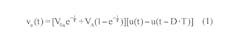
    Using the same RC filter, periodic-input pulse train, and designations as the referenced Idea for Design, Equation 1 shows the filter output when the driving source VA is non-zero:

    Electronicdesign Com Sites Electronicdesign com Files Uploads 2013 11 Eq 1
    When the driving source drops to zero, the output is given by:
    Electronicdesign Com Sites Electronicdesign com Files Uploads 2013 11 Eq 2
    In Equation 1 and Equation 2, the two starting conditions V0a and V0b are yet to be determined. A gating function with unit steps is also used. At steady state and at the switching boundaries, t = DT and t = T, so Equations 3a and 3b must hold:
    Electronicdesign Com Sites Electronicdesign com Files Uploads 2013 11 Eq 3
    This indicates that the end state of active duration with non-zero driving source must act as the starting state, V0b, of the inactive duration with zero drive. Similarly, the end state of the inactive interval must return to the same starting state, V0a, of the active segment. Using these facts and Equations 3a and 3b, we get:
    Electronicdesign Com Sites Electronicdesign com Files Uploads 2013 11 Eq 4
    In other words, cyclic starting states are actually known functions of driving source VA, duty cycle D, pulse period T, and time constant RC = τ. The steady state output in one cycle can be written as:
    Electronicdesign Com Sites Electronicdesign com Files Uploads 2013 11 Eq 5
    where the multiple-cycle output is given by:
    Electronicdesign Com Sites Electronicdesign com Files Uploads 2013 11 Eq 6
    Using the example of the previous Idea for Design, with VA = 1, D = 0.6, T = 20 μs, and τ = 50T, produces the steady-state results of the figure. The output dc level (Equation 7) is obtained by taking the average of Equation 5:
    Electronicdesign Com Sites Electronicdesign com Files Uploads 2013 11 Eq 7
    and confirms Equation 16 of the previous approach.

    The approach presented here gives the true steady-state output in compact, closed form with a high degree of confidence. The technique can be extended to other second- and higher-order circuits that are switched periodically among multiple states.2, 3

    Electronicdesign Com Sites Electronicdesign com Files Uploads 2013 11 Ifd2567 Fig
    Analysis shows that the steady-state output of this RC filter, when driven by a 50-kHz, 1-V, 60% duty-cycle PWM wave, is also periodic and stays within a narrow amplitude band.

    References

    1. “Graphically Determine The Output Signal Level Of An RC Filter,” Electronic Design, Oct. 3, 2013.

    2. Switch-mode Power Converters, Keng Wu, Elsevier, 2005, ISBN 13:978-0-12-088795.

    3. Power Rectifiers, Inverters, and Converters, Keng Wu, Lulu.com, 2008, ISBN 978-1-4357-2023-7.

    Keng C. Wu has a BS from Chiaotung University, Taiwan, and an MS from Northwestern University, Evanston, Ill. He has published four books and holds seven U.S. patents. He can be reached at [email protected].

    Continue Reading

    Solid-State Photorelay Tackles High Frequencies, ATE Signal Switching

    Maximizing Power from Solar Panels

    Sponsored Recommendations

    Designing automotive-grade camera-based mirror systems

    Dec. 2, 2023

    Design security cameras and other low-power smart cameras with AI vision processors

    Dec. 2, 2023

    Automotive 1 TOPS vision SoC with RGB-IR ISP for 1-2 cameras, driver monitoring, dashcams

    Dec. 2, 2023

    AM62A starter kit for edge AI, vision, analytics and general purpose processors

    Dec. 2, 2023

    Comments

    To join the conversation, and become an exclusive member of Electronic Design, create an account today!

    I already have an account

    New

    Tiny Sensors Simplify Full Body Motion Capture

    Design Resources Boost Embedded Development Projects

    Who is Using RISC-V?

    Most Read

    Observability Framework Exposes DDS

    Virtual Circuits Beat Out Quantum Computer

    Master Cell Balancing to Enhance EV Performance


    Sponsored

    Understanding SOA Curves to Operate at High Output Currents and Temperature

    Power density: Achieve more power in smaller spaces, enhancing system functionality at reduced system costs

    Time-Saving and Cost-Effective Innovations for EMI Reduction in Power Supplies

    Electronic Design
    https://www.facebook.com/ElectronicDesign
    https://www.linkedin.com/groups/4210549/
    https://twitter.com/ElectronicDesgn
    https://www.youtube.com/channel/UCXKEiQ9dob20rIqTA7ONfJg
    • About Us
    • Contact Us
    • Advertise
    • Do Not Sell or Share
    • Privacy & Cookie Policy
    • Terms of Service
    © 2023 Endeavor Business Media, LLC. All rights reserved.
    Endeavor Business Media Logo