Resonant Circuit Generates a High-Frequency Magnetic Field
This file type includes high resolution graphics and schematics when applicable.
Generating a high-frequency magnetic field can be quite a challenge due to an assortment of technical issues. At high frequency, magnetic-coil impedance is large. It requires a high-voltage and high-frequency generator to produce enough current through the magnetic coil. However, it’s difficult to generate high frequency and high current at the same time using conventional amplifiers and drivers. Classic series resonant techniques have been used for high-frequency magnetic-field generation.1 The resonant circuit proposed in this article will further boost coil current by 2X.
Classic Resonant Tanks
Figure 1 shows the series and parallel LC tanks. The series LC resonant tank features low impedance at resonance. The coil impedance cancels the capacitor impedance; thus, achieving low impedance enables high current through the LCR circuit. Up to now, the most practical and efficient way to drive high current through a magnetic coil is to use a series resonant circuit.1 No doubt, then, that the series resonant technique is often used for a high-frequency magnetic field generator.
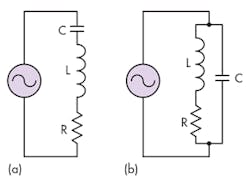
On the other hand, the parallel resonant LC tank’s impedance is maximized at resonance. At resonance, the current resonates between the coil and capacitor. The current passing through the magnetic coil is very high while the source current is very low; hence, high impedance. Consequently, the parallel resonant circuit amplifies the source current at resonance. The coil current is generally small in parallel resonance, even with the current amplification effect.
Current-Amplified Resonant
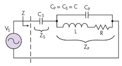
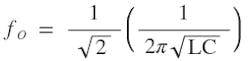
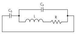
The new current-amplified resonant circuit features low impedance at resonance and current amplification in the magnetic coil (Fig. 2). This resonant tank is a powerful, high-frequency, magnetic-field generator. As will be discussed later, current amplification is two times the source or generator current. In addition, the current-amplified resonant circuit is an impedance transformer—at resonance, it transforms the resistance by a factor of four. Therefore, it increases the coil resistance by 4.
Resonant Conditions
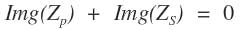
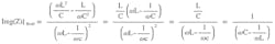
The condition for resonance is when the imaginary portion of the impedance, Z, is zero.
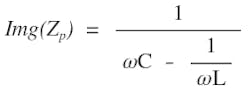
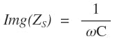
The resistance in Figure 2 is parasitic in nature and generally small. It has negligible effect on the resonance frequency. For the purpose of resonance-frequency calculation, R is ignored. As we will discuss later, smaller resistance is better a for high-strength and high-frequency magnetic field. The two capacitors are of equal value (CS = CP = C). From the Appendix, Equation A3, the imaginary part of a parallel resonant impedance ZP, is given in Eq. 3. The imaginary part of ZS is just a simple capacitor reactance:
(4)
Substitute Equations 3 and 4 into Equation 2 and it becomes:
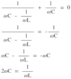
(5)
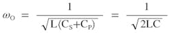
Solving for ω, which is the current-amplified resonant frequency ωO:
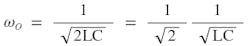
(7)
Recall, ωO = 1/√LC is the classic parallel or serial resonant. From Equation 6 and 7, the new current-amplified resonant frequency is 1/√2 times the classic LC tank resonant frequency. This is because there are two capacitors in the new resonant circuit.
Amplifying Current
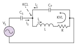
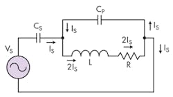
The most interesting feature of the new current-amplified resonant circuit is that it amplifies the magnetic-coil current twofold at resonance. That is, the electromagnet current is twice the source generator current. Refer to Figure 3, using the Kirchhoff’s voltage law (KVL) around the loop in the parallel tank. Again the small parasitic R is ignored.
(8)
Recall from Equation 6 that at resonance, ω = 1/√2LC. Insert Equation 6 into Equation 8.
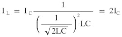
(9)
The magnetic coil current is twice as much as the capacitor CP or CS current (Fig. 3). In fact, the sum of CP and CS current is equal to the magnetic-coil current.
Now use Kirchhoff’s current law (KCL) to calculate the current at the node where all three currents (IS, IC, IL) are met:
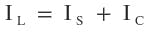
Since IC is half of IL:
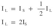
(11)
In summary, the coil current is twice as much as the signal-source generator current. For a given signal generator, the coil current is two times the maximum available current! This is a crucial feature for scientific apparatus that require a high-strength and high-frequency magnetic field. Figure 4 shows the current flow and how the resonant circuit amplifies current.
Resonant Impedance
As discussed above, at resonance the reactive (imaginary part) impedance is zero. The impedance is real (resistive) at resonance. Since ZS is reactive only, the real component of Z is coming from ZP. From Appendix Equation A2, the real part of Z is given as:
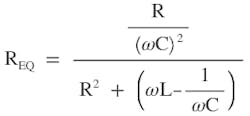
(12)
Recall that ω = 1/√2LC at resonance, and substituting it into Equation 12 and simplifying yields:
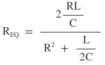
(13)
L/2C is much greater than R2; therefore, R2 is neglected. Thus, Equation 13 is reduced to:
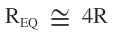
The current-amplified resonant circuit acts like an impedance transformer. It increases the high-frequency coil’s resistance by a factor of 4. This new resonant circuit is most advantageous for high-current and low-resistance magnetic coils. It enables high-frequency magnetic-field generation with low source voltage.
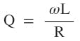
Quality-Factor Q
The most important feature of this new current-amplified resonant circuit is its ability to boost current by a factor of 2 for free in order to generate a high-frequency magnetic field. Therefore, the quality factor Q does not impact the current amplification; instead, it affects the resistance. For completeness, Q is discussed here.
The ac voltage source, VS, is equivalent to a short circuit from the ac signal model’s point of view. The current-amplified resonant tank in Figure 2 is redrawn in Figure 5 from the signal model (or energy) point of view. As can be seen, the two capacitors are in parallel and form a single parallel resonant tank. Recall from the classic parallel tank that the Q is equal to:
(15)
Therefore, the Q of the current-amplified resonant tank is the same as the classic parallel resonant tank.
As a confirmation of the previously discussed resonant frequency, the resonant frequency from Figure 5 can be easily found by using the classic parallel tank equation, after taking into account CP = CS = C:
(16)
Simulation Results
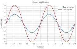
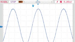
To confirm the new resonant-circuit mathematical model discussed above, a Spice simulation tool was used to simulate the current-amplified resonant tank in Figure 2. At resonance, the source current is 5 A peak and the coil current is 10 A peak (Fig. 6). This confirms the current-amplifying effect of the new resonant tank. Using a 10-µH and two 1.26-nF capacitors, the calculated resonance is 1.0026 MHz. The simulated resonance is 1.025 MHz (Fig. 7).
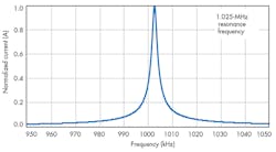
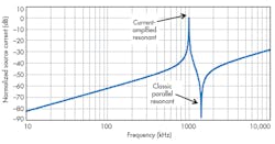
In the simulation, the coil resistance is 125 mâ¦, the source voltage is 2.5 V, and the source current is 5 A. This also confirms the tank equivalent impedance is 500 mâ¦, as calculated in Equation 14: 4 × 125 m⦠= 500 mâ¦. Using the simulation tool, increasing the resistance to 10 ⦠does not change the current amplification factor. Figure 8 plots the source-generator current versus frequency of the current-amplified resonant circuit. It reveals two resonances—the new resonant and the classic parallel resonant. The current-amplified resonant frequency is lower than the classic resonant frequency by a factor of 1/√2.
High-Frequency Magnetic-Field Experiment
To verify the magnetic-coil current-amplification effect, a real coil (inductor) was used. The current generator source is the TS250 high-current function generator amplifier2 from Accel Instruments. As shown in Figure 9, the coil is a 100-µH high-current inductor. The two 10-nF capacitors are rated for 1 kV.
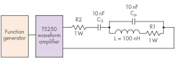
A series 1-⦠resistor (R1) is inserted to monitor the coil current. Another current-sense resistor (R2) is used to monitor the source current. Measuring current requires measuring the voltage drop across R1 and R2. During the experiment, both 10 m⦠and 100 m⦠have been used for R1. For low resistance, the voltage across the sense resistor is so small that the high-frequency magnetic field generated by the coil was interfering with the voltage measurement. Increasing R1 to 1 ⦠showed no sign of interference.
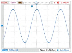
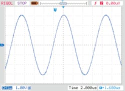
The initial source voltage from the TS250 waveform amplifier was set to 10 VP-P and the initial frequency set to the calculated resonant frequency of 112.5 kHz. Then the frequency was slowly changed until maximum current was observed. This is the 116.5-kHz current-amplified resonant frequency. Subsequently, the voltage amplitude was slowly increased to obtain higher current. At about 30 VP-P, the source current is about 3 AP-P (Fig. 10). As shown in Figure 11, the magnetic coil current was 6 AP-P. As predicted, the coil current is amplified by a factor of 2.
The theoretical current-amplified resonant-circuit impedance is 4 ⦠(not including R2), which is calculated using Equation 14. The R1 resistance is amplified by a factor of 4. Adding R2 resulted in a total theoretical resistance of ~5 â¦. However, the data indicates that 30-VP-P voltage resulted in 3 AP-P, which implies the total impedance is 10 â¦. The magnetic-coil dc resistance is specified at 25 mâ¦. It’s therefore assumed the coil’s ac 116-kHz resistance is much higher due to the skin effect at high frequency. In addition, the capacitors add parasitic resistance. When designing high-frequency magnetic coils for the current-amplified resonant technique, it’s important to keep the ac resistance as low as possible.
Conclusion
The novel current-amplified resonant circuit presented here offers a powerful technique for generating high-frequency magnetic fields in scientific and R&D apparatus. The mathematical model predicted the current-amplifying effect in the high-frequency electromagnet. Both simulations and lab experiments confirmed the coil current is amplified by a factor of 2.
This file type includes high resolution graphics and schematics when applicable.
References:
1. “High-Current and High-Frequency Electromagnet Using Resonant Technique,” Accel Instruments.
2. “Waveform Amplifier for Function Generator,” Accel Instruments.
Appendix – Parallel Resonant Impedance Derivation
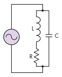
Figure A. The classic parallel resonant circuit consists of RLC to calculate impedance and reactance.
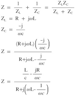
(A1)
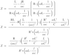
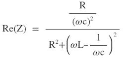
(A2)
(A3)
About the Author
KC Yang
Product Marketing Engineer
KC Yang is a product marketing engineer at Accel Instruments, which specializes in high-frequency and high-current amplifiers for general lab bench testing. He received a Master of Science in electrical engineering from University of California, San Diego, and a Bachelor of Science in physics from Washington State University. He has published numerous application notes and article.
Comment About the Article
To join the conversation, and become an exclusive member of Electronic Design, create an account today!

Leaders relevant to this article: