
Back in 2011, shortly before Bob Pease died, Julian Driscoll expressed confusion about the Linear Technology LTZ1000 ultra-stable low-noise voltage reference. If Pease was familiar with the competitor’s part, he would have helped; Pease was that dedicated to his readers. Unfortunately he didn’t have any experience with the part, and wrote back:
“Julian, you are right. The LTZ1000, and how to apply it properly, is not well explained; So write a note to Jim Williams at LTC, 1630 McCarthy Boulevard, Milpitas CA 95025. Ask him, that if he has any good app notes on how to apply the LTZ1000, you can design it in. (If not, not.). Mail it to Jim - he don't do e-mail. He'll reply (if you mention my initials...) Next: After you get it built - how the hell you gonna evaluate and test it? That's beyond me, this week. Did you see my column on stability? A related topic. A set of 16 LM199AH20's, per that column with outputs averaged, is probably almost as good as the LTZ1000. It depends on how much study and work you want to put into it.”
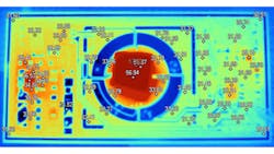
The LTZ1000 is a deceptively simple part. It consists of a Zener diode, a temperature-compensating transistor, an on-chip heater, and a sense transistor that you can use to control the heater. It is an ovenized voltage reference. If you heat the part up and hold a consistent temperature, then the voltage output is unaffected by changes in ambient temperature. It is considered the most stable voltage reference short of a standard cell. Glen Brisebois, an application engineer at Linear Tech, points out “The LTZ1000 is still at the heart of all the highest-grade meters (Fig. 1), until the Josephson junction takes over. Have you ever priced a Josephson junction meter? I haven't. An LTZ1000A is $54.50.”
Tim Regan, a retired applications manager at Linear Tech, notes, “The main interest to everyone out there is how to get the best performance out of it...and how to prove it. Is the actual long-term handful of ppm's of drift coming from the reference or the meter measuring it? People have spent a better part of their careers chasing such reference perfection.”
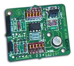
He goes on to note that the LTZ1000 is pretty much the only game in town, “National/TI obsoleted the LM199, so the LTZ1000 is the only replacement in the industry that I know of. It has quite a following, too, with one guy in Europe making a very cool looking PCB layout with slots (Fig. 2).”
The datasheet for the LTZ1000 can be a bit daunting. It dives into detail, taking for granted we non-experts understand the design intent.
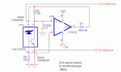
Brisebois explains, “The simple loop circuits will work at low noise, but not low tempco. By far the most popular circuit is the full ‘7V Positive Reference Circuit’ (Fig 3). One useful thing to understand (it took me 15 years) about the LTZ1000 is that pin 4 is the p-substrate. All the other pins operate above that (which is why you want the heater a diode-drop up) ... except for the mysterious case of pins 6 and 7, which operate 0.6V below the substrate.” Carl Nelson, the LTZ1000 designer, notes he did this to allow for a true subsurface Kelvin connection to the bottom of the Zener, reducing its resistance.
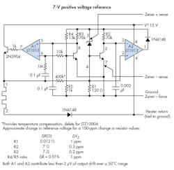
I once showed Bob Pease a schematic of a lab power supply, and he said “I would have to redraw that thing to even begin to understand how it works.” That is good advice. So I redrew the 7-V reference design of Fig. 3 as a conceptual design in OrCAD’s PSpice (Fig. 4).
Rather than show the layout considerations, like running separate traces for the three circuit commons, this is just how the circuit is intended to work. The way I have drawn it, you can see there are two circuits. The Zener and transistor are combined with a few discretes and an op amp to make the reference. The second circuit takes that reference voltage and compares it to a second transistor’s base-emitter junction to servo the heater to your desired temperature. I changed the value of C1 to 0.022 μF instead of the datasheet value of 0.002 μF. Glen Brisebois notes, “At 0.002 μF, the circuit will be stable, but a little ringy. Of course, being a dc gizmo, you won't see a ring but just a little extra noise at high frequency.”
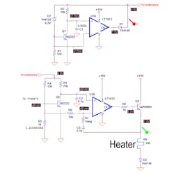
Many engineers don’t think a dc circuit like this needs compensation, but Brisebois notes, “It's a dc reference, of course, so people think it can't have ac problems. But you bet without compensation, it's gonna oscillate, and with inadequate compensation, it's going to peak up the noise, ring when sampled, etc. etc.”
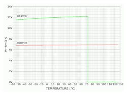
The Spice output is instructive since it shows the dc bias points. You can also do a dc sweep of temperature that shows the inherent stability of the reference without ovenization, as well as the sharp response of the heater servo circuit as the temperature sweeps past the set-point you create with the R4/R5 voltage divider (Fig. 5).
I learned from the dc sweep and set the dc temperature at 72.77482°C so that the heater op-amp output was in the middle of its power rails. You can infer from the precision of that temperature how well the circuit works to keep a constant temperature. The transistor used in the actual part would stabilize the temperature at 60°C, unlike the 2N2222 I used.
Note that while LTZ1000 is ultra-stable, its initial accuracy might range between 7.0 and 7.5 V. Also note that it takes a few minutes for the LTZ1000 to warm up and reach set-point. You might add circuits to sense when it is stable, but perhaps better to not touch the LTZ1000 and just do digital sampling or a timeout to make sure the part is warmed up.
Also note that the temperatures of the two transistors track each other very closely. The VBE that the heater circuit servos to, will also change the VBE of Q1. However, since the combination of the Zener and Q1 have offsetting thermal coefficients, the change will not be great. It’s another factor in the variable initial accuracy of the part. If you change the operating temperature with the ratio of R4 and R5, it will change the output voltage.
With the design intent figured out, you can draw a schematic intended for your printed-circuit-board (PCB) layout (Fig. 6). The datasheet schematic uses two little arrowheads to indicate a Kelvin connection to the circuit. That is not accepted practice; in Fig. 6, the connections are drawn as wires. A note makes it clear that they are Kelvin connections. The schematic shows the heater and amplifier commons separate, so those currents do not interfere with the reference output.
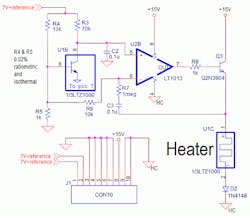
Some folks put a dummy resistor in the schematic to separate those grounds into different nets. However, Mark Thoren, staff scientist at Linear Technology says, "Dummy resistors separating 'grounds' are a recipe for disaster, and I see disasters related to this practice all the time. One of the first things to look for when reviewing a customer's schematics is multiple ground symbols without a good reason for them."
So watch those multiple grounds, and remember that Henry Ott, the noise expert, recommends you have one reference plane (he hates the term ground plane, since there is no earth ground connection). Ott says you use placement and routing discipline to make sure the delicate circuits stay unaffected by other circuits and external noise. Thoren remarks, “When customers call with grounding and noise problems, this article by Henry Ott has saved me countless hours of typing. I say ‘read this and call me in the morning, and it often answers 3/4 of the questions.’ I hand all new Linear Tech FAEs [field application engineers] a paper copy on their first visit to Milpitas.”
Do be aware of the return currents causing drift problems. Nelson comments, “Current out of pin 7 is about 6.5 V/R2 + 6.5 V/R3 = 186 μA. Current out of R5 is about 550 μA. Current from R1 (same as the Zener current) is about 4 mA. These currents should be routed separately to the low side of the reference output. If a single trace is used, and the trace resistance is 0.4 Ω, voltage drop in the trace will be 1.9 mV. Copper has a thermal coefficient of 0.0038/°C, which generates 7 μV/°C in the trace, equal to about 1 ppm/°C in the reference. This is about 20 times higher than the expected drift of the part’s design intent.”
Another common problem with semiconductor company schematics is they keep the part as one symbol. It would be better to break that symbol into separate chunks so the design intent of the Spice schematic can be maintained with the PCB layout schematic. OrCAD 9 does this with “heterogeneous” parts. It was introduced to deal with logic packages like hex inverters, but there is nothing that says the different parts have to be identical.
Here, I have made one part with the Zener and temperature-compensating transistor, one part with the sense transistor, and one part with the heater. They all use the same 8-pin TO-5 footprint, so now people can understand your schematic, but it still properly controls the layout. Like the Spice schematic, I kept a strict adherence to “inputs on the left and top, outputs on the right and bottom.” Schematics have a flow just like text. I also did not use earth ground symbols, since this circuit does not return to the third pin of your wall socket. The little triangle meaning “Common” or “Return” is more correct.
One feature that makes the LTZ1000 low in noise is it incorporates a buried Zener. There is a good description of this in Linear Technology application note AN82. As the name implies, semiconductor companies make a buried Zener underneath the top surface of the die. In this respect, it is similar to JFETs (junction field-effect transistors) used in some op amps. Since these devices are “buried” underneath the top layer of the die, there are fewer crystal defects and noise-generating sources.
When you design precision circuits like this, you also have to be aware of thermocouple effects. I thought I understood how a thermocouple works until I read Martin Rowe’s explanation. Like many engineers, I thought there was some magic mojo at the bead where two dissimilar wires are connected. I thought this bead made a tiny voltage proportional to temperature. I should have known better. The bead is welded metal and full of metallic valence electrons.
What makes a thermocouple work is the Seebeck effect. A wire that has a temperature gradient from one end to the other will generate a tiny voltage. Different metals have different voltages. So a thermocouple is two different metals that are connected at one end, and by definition, at the same voltage there.
But as the same temperature gradient applies to the two different metals, an offset voltage will be at the other end. This is why you kept the other end in an ice bath in the old days. It made the two loose ends isothermal, and increased the temperature gradient, to give a bigger signal. Nowadays, you just need to keep the loose ends isothermal and you can measure that temperature with a silicon or other type of device that’s more convenient than an ice bath.
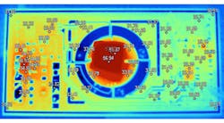
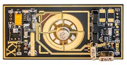
So when designing the LTZ1000 circuit, it’s OK to have temperature gradients, as long as they are the same for the +reference and âreference traces. In addition, you need to have the same number of dissimilar metal junctions in the traces. You would not use tin-lead solder on one, and tin-antimony on the other trace. Each of those dissimilar junctions must also be isothermal with its mate in the other trace. This is why many designs have slots cut in the board, both to isolate the LTZ1000 from PCB stress and ensure the temperature gradients on the traces are the same. Illya Tsemenko, who did the board in Fig. 2, has done some great work taking thermal images of the design (Fig. 7).
Another thermal consideration is enclosing the PCB to keep it away from drafts that would create those dreaded non-uniform temperature gradients. It’s also a good idea to insulate the part and PCB with styrofoam. This can lessen temperature gradients, but more importantly, the part will use less power to stay at its set-point temperature. I suppose the ultimate would be a vacuum enclosure. Nelson notes, “The LTZ1000A uses a special high-thermal-resistance die-attach material that reduces heater power needed by about 5:1 compared to the LTZ1000.”
Well, it’s easy to see why Julian had trouble taking in all of the LTZ1000’s complexities and subtleties. Hopefully this article will help you understand the care and feeling of this remarkable part, still in use despite being invented back in 1984. Don’t be shy about reaching out to the applications people at Linear Tech or any other semiconductor company. They want to hear from customers so they can understand what you need and how you use their parts. Until then, keep designing.

About the Author

Paul Rako
Creative Director
Paul Rako is a creative director for Rako Studios. After attending GMI (now Kettering University) and the University of Michigan, he worked as an auto engineer in Detroit. He moved to Silicon Valley to start an engineering consulting company. After his share of startups and contract work, he became an apps engineer at National Semiconductor and a marketing maven at Analog Devices and Atmel. He also had a five-year stint at EDN magazine on the analog beat. His interests include politics, philosophy, motorcycles, and making music and videos. He has six Harley Sportsters, a studio full of musical instruments, a complete laboratory, and a video set at Tranquility Base, his home office in Sun City Center Florida.
Comment About the Article
To join the conversation, and become an exclusive member of Electronic Design, create an account today!

Leaders relevant to this article: