
Download this article in PDF format.
Light-emitting diodes have become the lighting source of choice for almost all illumination applications. Incandescents, fluorescents, CFLs, and other types are fading away in favor of the almighty LED. LEDs are now brighter and use less power than any other lighting source. And their prices have decreased to an acceptable level. The result has been increased adoption of LEDs in home, auto, and other applications.
Perhaps the main challenge for designers is learning how to power the LEDs. For some simple applications, it’s just applying a forward bias voltage through a current-limiting resistor. However, driving LED strings and controlling brightness require much more sophisticated circuitry. Then there are the matters of driving LCD backlighting. In addition, automotive applications demand special measures because of the extreme power-supply conditions that occur. Here’s a look at these applications and related solutions.
Sponsored Resources:
- Drive your design forward with the LED Driver Basics Series
- Backlighting and Display Concepts Made Simple
- How to: LED reference design for automotive applications
Powering an LED
A major point to emphasize is that the LED current must be controlled to set the brightness level. Therefore, the most desirable LED driver is a current source. A simple arrangement is shown in Figure 1. The resistor sets the current level. Such linear current sources are satisfactory for low-power applications, but they dissipate too much power and heat when multiple LEDs are used and high brightness is necessary. As a result, designers have found that the best drivers are switch-mode types.
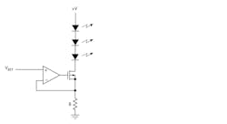
1. A linear-current-source LED driver works best in low-power applications.
Basic LED Driver Topologies
Modern LED driver circuits resemble a switch-mode regulator or dc-dc converter. Most common driver varieties use some of the same topologies as used in these basic regulator dc-dc converter circuits. Figure 2 shows the most common topologies, all of which use MOSFET switches.
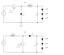
2. Common dc-dc converter regulator switch-mode topologies are the buck (a) and boost (b).
The buck driver (Fig. 2a), which is the most common, has an output that’s always lower than the input. The boost driver (Fig. 2b) produces an output that’s higher than the input. The buck-boost can produce an output voltage that’s either higher or lower than the input voltage.
There are several variations of the buck-boost, such as the floating buck-boost, the SEPIC, and the Cuk. The SEPIC and Cuk both require two inductors that add cost and take up more space. The SEPIC (shown in Fig. 4 below) is discussed later.
LED Dimming
A common need in LED lighting is dimming—controlling the brightness over a range from full off to the full brightness. Multiple dimming techniques have been developed using both linear and digital methods. In both, the brightness is determined by the average forward current in the LEDs. Over the current range of most LEDs, the relationship between average current and brightness is linear. Only at the high and low levels of current does the relationship become nonlinear.
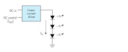
3. A linear-current regulator driver IC sets the brightness by applying a dc input control voltage.
Linear dimming is accomplished with a linear-current regulator IC (Fig. 3). A dc voltage controls the circuit, producing a linear current and brightness variation. Dimming ratios from 10:1 to 250:1 can be realized. While linear dimming is the simplest and easiest to implement, it may not fit the application. Some use cases require a wider dimming ratio that could be as high as 1000 or more to 1. Furthermore, linear dimming may produce an undesired color shift in color LEDs over the dimming range. It’s possible to mitigate that with pulse-width-modulation (PWM) dimming.
The average current in the LEDs can be varied with PWM by changing the duty cycle of the applied dimming pulses. The frequency of the pulses must be fast enough to prevent the human eye from perceiving flicker in the light. A pulse frequency of 200 Hz or higher is usually sufficient. The pulse is applied to a switching regulator type of dimming IC; the switching frequency of the regulator is significantly higher than the dimming frequency. The regulated current output is applied directly to the LED. Other arrangements use an external MOSFET to speed up the dimming response and minimize nonlinear brightness response. Figure 4 shows one arrangement.
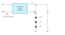
4. LED dimming is accomplished with a switching current regulator using a variable duty-cycle PWM input from a microcontroller or other source. The external components enable faster switching at higher frequencies.
Backlighting
LEDs are widely used to backlight liquid crystal displays (LCDs), such as those used for typical laptops. One common arrangement is an array of 60 white LEDs made up of six strings of 10 series-connected LEDs. Each string needs a driver that can be utilized for dimming. Light guides and diffusers are used to spread the light uniformly across the screen.
Backlights must be super bright to give sufficient brightness to an LCD. As a result, they generally consume a considerable amount of power. When selecting a driver, efficiency is an important factor.
The two basic ways to control dimming are linear current variation and PWM. The linear version works well, but it’s limited because of the difficulty in delivering very small currents. The nonlinearity of the LEDs limits the minimum brightness level.
A widely used driver is the dc-dc converter with PWM. The PWM approach varies the duty cycle of applied pulses to control the average LED current and the brightness. Though this method can achieve very small duty cycles and good low brightness resolution, it suffers from inefficiency and high switching noise at the higher duty cycles. The solution is a hybrid approach that uses both linear current variation and PWM methods to achieve the optimum dimming control over the full range of brightness. There are LED driver ICs that incorporate this hybrid dimming method.
Automotive Applications
Most of the lighting in new vehicles is via the LED. Common automotive applications are daytime running lights, fog and headlamps, and turn signals. Because of the wide output variation of the main 12-V battery source under different conditions, special driver circuits are needed to maintain brightness.
The main power bus voltage is usually a bit over 13 V during normal battery charging. Under warm crank conditions, this voltage can drop to about 7 or 8 V. And in load dump conditions, the voltage may rise to 16 V. Transients can peak at about 42 V. In general, LED drivers need to be good regulators.
One of the best regulator/dc-dc converter topologies to deal with this scenario is the SEPIC. Its configuration produces a constant output voltage even though the input voltage may vary above or below the output voltage. Figure 5 shows the basic configuration. Its key characteristic is two inductors. A preferred arrangement is to use coupled inductors that form a transformer with a 1:1 ratio. Such an approach makes the circuit more efficient and minimizes space on the PCB.
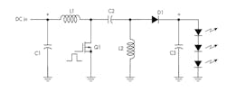
5. A SEPIC regulator driver circuit is a good fit for automotive lighting applications. Its buck-boost capability readily deals with the wide voltage fluctuations of the battery supply bus.
A typical switching frequency is 350 kHz. When the MOSFET Q1 turns on, the input voltage is applied to the input inductor storing energy as a magnetic field. The 1:1 coupling puts the input voltage across the second inductor; therefore, the series capacitor C2 charges to the input voltage. The output voltage is supplied by the previous charge on the output capacitor C3.
When the MOSFET is switched off, the polarities of the inductor voltages reverse. During this time, the shunt inductor L2 charges the output capacitor. The input voltage, series inductor L1, and series capacitor C2 voltages combine and charge the output capacitor C3 to support the output voltage. Feedback and PWM control of Q1 aren’t shown.
One SEPIC LED driver IC on the market is Texas Instruments’ TPS92691-Q1. It can supply a constant 12 V at 3 A under widely varying input conditions. Also available is the PMP15027 reference design using this IC.
Learn More to Design Better
TI offers a complete series of training videos that present the fundamentals of LEDs and driver topologies, plus analog and PWM dimming methodologies. Other videos cover LCD operation and driving as well as backlighting. A video on automotive applications discusses the SEPIC driver topology and explains the design challenges in dealing with situations like cold crank, warm crank, or load dump. Learn just what you need at your own pace.
Sponsored Resources:
About the Author

Lou Frenzel
Technical Contributing Editor
Lou Frenzel is a Contributing Technology Editor for Electronic Design Magazine where he writes articles and the blog Communique and other online material on the wireless, networking, and communications sectors. Lou interviews executives and engineers, attends conferences, and researches multiple areas. Lou has been writing in some capacity for ED since 2000.
Lou has 25+ years experience in the electronics industry as an engineer and manager. He has held VP level positions with Heathkit, McGraw Hill, and has 9 years of college teaching experience. Lou holds a bachelor’s degree from the University of Houston and a master’s degree from the University of Maryland. He is author of 28 books on computer and electronic subjects and lives in Bulverde, TX with his wife Joan. His website is www.loufrenzel.com.
Comment About the Article
To join the conversation, and become an exclusive member of Electronic Design, create an account today!

Leaders relevant to this article: