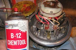
I bought a used hy-gain HAM-IV at the Silicon Valley Electronics Flea Market (Fig. 1). It’s designed for medium-sized ham antennas and is more an industrial product than a consumer one.
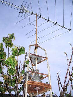
1. The hy-gain HAM-IV antenna rotator used on a VHF TV antenna. While this setup captivates the antenna mast in the base, the HAM-IV is structural and does not need the added support.
It has a fixed inner section surrounded by top and bottom housings stabilized by a dual row of large ball bearings (Fig. 2).
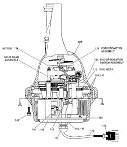
2. The HAM-IV, sometimes referred to as the HAM-4, is a well-built unit. The guts of the unit are stationary. The upper (102) and lower (103) outer housings rotate together, supported by two rows of ball bearings (104, 105). The lower part of the stationary guts has a solenoid brake (136). The upper section has the electric motor and gear-train. It also holds the limit switches, and a potentiometer that allows a read-out meter on the control box to show the rotation in terms of cardinal (N, S, E, W) direction. (Courtesy of hy-gain)
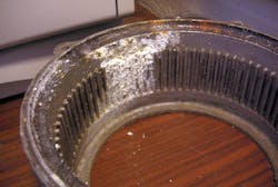
The top housing holds one row of ball bearings at its periphery (Fig. 3). Working in concert with the bearing in the bottom housing, it makes the unit structural. The fixed inner part can be fastened to the antenna mast base; the rotator will fully support the antenna even on a long pole. Unfortunately, the bearing races are molded into the pot-metal housings, which are a bit soft for a bearing race. On this particular unit there was brinelling of the races, which showed radial loads that were large enough to cause the steel ball bearings to dent the housing race.
3. The upper housing has one of the bearing races, as well as three saddles that engage tabs on the steel ring gear that does the rotation. The small feature in the center engages the wiper arm tab of the potentiometer.
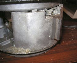
Carburetor cleaner from the auto parts store cleaned the old grease off the bearing areas (Fig. 4). The ball bearings and their plastic races also clean up well, despite the hard use this unit has seen (Fig. 5).
4. Carb cleaner removes all of the old grease from the outer housings and this stationary inside part. The edge of this part has bearing races molded into the top and bottom to retain the outer housings. Also visible is the limit switch assembly and the rotation-indicator potentiometer.
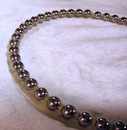
5. The ball bearings are captivated by a molded plastic cage. This retains the balls and allows for easier assembly. The carburetor cleaner works its magic on the balls, too.
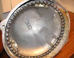
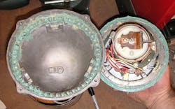
The lower housing had some corrosion (Fig. 6). The grooves on the interior of the housing engage with a solenoid-operated brake blade (Fig. 7). This keeps wind loads on large antennas from back-driving the motor.
6. The lower housing bolts to the upper housing and they rotate together. The grooves in the lower housing are where the brake blade engages to prevent the unit rotating in the wind. I suspect the corrosion was from the unit sitting on its side in storage with some moisture inside.
7. The lower part of the stationary interior section has the solenoid-operated brake blade that engages with the grooves in the lower housing.
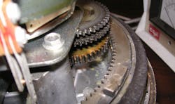
The electric motor in the unit runs on 24 V for safety. The motor output is geared down and eventually drives a large steel ring gear with tabs that engage the outer housing (Fig. 8). The ring turns with the outer housings while the guts of the unit are stationary.
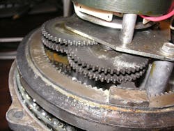
8. The gear-train before cleaning and lubrication. The are several spur gear reductions prior to driving the large steel ring gear. In the foreground is one of the tabs on the ring gear that engages with the saddles molded into the top housing.
A potentiometer in the stationary part engages a pocket in the top of the upper housing (Fig. 9). The pot goes to a meter on the control unit that shows the cardinal direction the rotator is aligned to. The wiper of the potentiometer is spring loaded. It allows the wiper to maintain contact as it follows the up and down helix of the windings. The spring also supplies compliance for the serrated tab that engages the top housing. This allows the unit to be assembled in an arbitrary rotation.
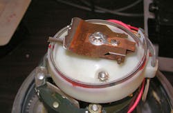
9. The spring-loaded potentiometer feeds back the rotor position to a meter on the control box inside the house. The copper foil provides a ground path to the outer housing. The serrations on the wiper drive tab will nestle into the small pocket in the top housing, even if it is not aligned initially.
When the unit is rotated in testing, the ridges in the serrated section will ride up and over the molded-in feature of the top housing visible in Fig. 3. Once the serrated section of the potentiometer tab settles into the grooved feature in the top housing, the spring force is high enough so that the wiper is retained in position to the top housing. It’s a rather involved, albeit clever, way to get the housing aligned to the potentiometer.
10. With the races and gears lubricated with waterproof marine grease, the unit can go back together. Despite thinking the potentiometer wiper would self-align, I did try to install it to line things up properly. The grease is thick enough to retain the ball bearings if you flip the top housing over. But by holding the stationary inner part with the help of a few long bolts, you can flip over the bottom and drop it onto the top housing with no chance of dislodging the balls.
Waterproof marine grease on the bearing races prepare the rotator for many more years of hard use (Fig. 10). Fortunately, my application of rotating a VHF television antenna was a very light load. When I moved to Florida, I gave the antenna and mast to a friend who is a ham radio aficionado. The rotator and control box are still working well, with a much larger antenna.

About the Author

Paul Rako
Creative Director
Paul Rako is a creative director for Rako Studios. After attending GMI (now Kettering University) and the University of Michigan, he worked as an auto engineer in Detroit. He moved to Silicon Valley to start an engineering consulting company. After his share of startups and contract work, he became an apps engineer at National Semiconductor and a marketing maven at Analog Devices and Atmel. He also had a five-year stint at EDN magazine on the analog beat. His interests include politics, philosophy, motorcycles, and making music and videos. He has six Harley Sportsters, a studio full of musical instruments, a complete laboratory, and a video set at Tranquility Base, his home office in Sun City Center Florida.
Comment About the Article
To join the conversation, and become an exclusive member of Electronic Design, create an account today!

Leaders relevant to this article: