Download this article in PDF format.
A T-coil is a special form of an inductive peaking circuit that will extend an amplifier’s bandwidth and speed up the output signal rise-time. The circuit uses a coupled inductor and a small bridging capacitor (Fig. 1). A T-coil can double the bandwidth of an amplifier. You can think of the inductor as steering input current into the capacitive part of the load, so it charges up more rapidly. The small bridging capacitor ensures that the input impedance of the T-coil is constant and resistive.
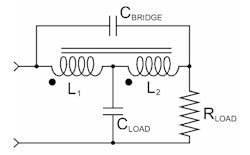
1. A T-coil uses a coupled inductor, essentially a transformer with three leads. It can double amplifier bandwidth, and the bridging capacitor gives it a constant input impedance. The CLOAD might be an input impedance or the capacitance of an ESD diode in a SerDes chip. The RLOAD might be a transmission line or impedance-matching resistor.
If the T-coil seems too good to be true, consider a simple RC load (Fig. 2 green). You can see the source impedance must deliver current to both the resistor and capacitor. Now imagine you have a switch that you can close once the capacitor charges up (Fig. 2 red). All of the current from the source will go to charging up the capacitor, and once charged, closing the switch at the precise time will get you near the final value faster.
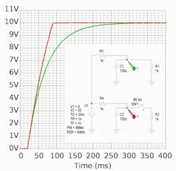
2. The capacitor in an RC load slows down the response from a step input (green). If you had a timed switch to the resistor, all of the input current would charge the capacitor, speeding up the response (red).
That is what the inductor does in an inductive peaking circuit. It shunts any rapidly changing input current to the capacitor, letting the resistor “catch up” after a necessary delay. Those delays are the cost of using these circuits. The T-coil is a useful form of inductive peaking since the bridging capacitor makes the input impedance nearly constant.
Teeing Up T-Coils for Analog—and Digital—Use
Tektronix engineer Bob Ross designed T-coils into the company’s analog oscilloscopes from the 1960s onward (Fig. 3). The advent of digital oscilloscopes does not mean T-coils are obsolete, though. Ross now shows how IC designers can improve the speed of their SerDes (serializer-deserializer) chips. While Tek oscilloscopes used discrete coils and capacitors on a PCB (printed circuit board), the SerDes chips utilize spiral inductors and on-chip capacitors. The T-coils can help overcome the slow-down from capacitive loads due to the ESD (electrostatic discharge) protection diodes on the IC die. ESD diodes are essential to prevent chip damage due to handling and external overvoltage events.
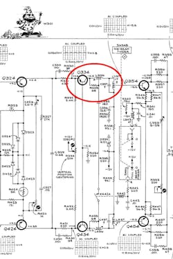
3. This part of the vertical amplifier schematic from a Tektronix 454 oscilloscope shows the T-coils used to improve bandwidth. The cheeky Tek engineers drew a wizard on the schematic, reference designator W301, to imply the speedy magic of their trade-secret T-coil designs. (Courtesy of Tektronix)
In addition to extending the bandwidth of analog oscilloscopes and improving the performance of high-speed digital I/O, T-coils are also very useful for tapping transmission lines (Fig. 4). The constant input impedance will allow you to daisy-chain several devices and those devices can have different input impedance—you just adjust your T-coil values.
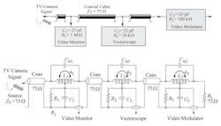
4. The constant input impedance of T-coils make them useful to distribute video to multiple drops. In this example from Starič and Mangan’s book, "Wideband Amplifiers," pp 2.49-50, the three video components all have different input impedance, but the T-coils provide for them all.
I built a simple PSpice circuit of a T-coil to show its performance (Figs. 5 and 6).
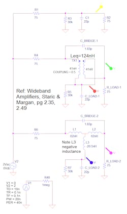
5. This PSpice schematic simulates the middle section of the above video distribution network. The top circuit represents the RC input impedance of the vectorscope. The middle circuit uses a coupled inductor modeled by a simple transformer. You set the “k” value to 0.5. The clumsy wiring shows the proper connection; you could edit the part to make wiring cleaner. The bottom circuit shows the three-inductor equivalent circuit. Note the leg of the “T” is a negative inductance.
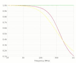
6. The frequency response plot of the schematic shows the speed improvement of the T-coils compared to the RC load (yellow). The equivalent circuit has identical output, so the blue and violet traces are underneath the red and green traces.
You can tweak the inductor and capacitor values to give a Butterworth or Bessel response. In the time domain, you can get faster rise-times by allowing more overshoot (Fig. 7).
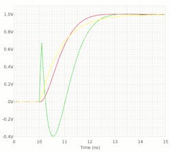
7. The transient response of the T-coil schematic: Compared to the RC load (yellow), the coupled inductor takes current from the 75-Ω load resistor, reversing its polarity momentarily (green), in order to speed up the rise-time (red).
One drawback of T-coils is the precise nature of the values that you need to obtain to get the intended performance. In the above example, taken from the book Wideband Amplifiers, the bridging capacitor is 1.83 pF. It’s hard to find a discrete capacitor with that small of a value. You are lucky to get 5% tolerance, not two significant digits. Most likely you will be using a stray capacitance you intentionally design into the circuit board layout.
You will also have to deal with real transformers, not models for Spice, or the ideal math. Those real transformers have inter-winding capacitance you might use as the bridging capacitor, as long as it is not too high to begin with. The Spice simulation above used a coil coupling factor, k, of 0.5. That might be hard to achieve in a real transformer, so that means more calculations and tweaking and compromise.
Those Tek analog scopes needed factory technicians to tweak all of the values to make up for strays and component tolerance in order to ship the product. T-coils in IC design can take advantage of the excellent repeatability of semiconductor processes, so that the circuit values are precise. No matter, it’s good to keep in mind this fascinating simple circuit; the analog principles behind it are timeless.
Talking with Lee at the eFlea
While at the Silicon Valley Electronic Flea Market in May 2018, I chatted with Stanford professor Tom Lee (Fig. 8). Professor Lee, a very hands-on electronics buff, knew of the T-coils in analog Tektronix oscilloscopes. There was nothing documented in the literature about the theory behind them; Tek kept the design methodology secret. So, Lee worked out the math behind T-coils for himself.
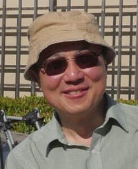
8. Stanford professor Tom Lee at the May 2018 Silicon Valley Electronics Flea Market, held at the Fry’s parking lot in Sunnyvale. Professor Lee has been researching the history and application of T-coils.
A Tektronix engineer, whose name Lee can’t recall, wrote him and asked who at Tek told Lee about the T-coil derivation. Lee told him, “I did this independently, since you guys never published this stuff.” The Tek engineer said T-coils were a Tek trade secret, to which Lee responded, “I’ve got blood-soaked pages to prove that I did this on my own, because I did it wrong many more times than I did it right.” The Tek engineer then engaged in some good-natured ribbing that Lee only solved the symmetrical case, where both coils have the same value.
That engineer referred Lee to John Addis, of the Tektronix Museum near Portland. The engineer said that Addis was “Mr. T-coil.” Addis was Tek's most prolific and able designer of T-coil-based amplifiers, but he pointed Lee to Bob Ross as the engineer who had derived the equations. Addis then introduced Lee to Ross. Professor Lee recounts the story:
“That started a friendship with Bob, who told this amazing story that starts in China in the 1930s. There was this gifted engineer, K.T. Wang, who was way too smart to work on just his power plant management job. He made up electrical engineering brain teasers for himself and then solved them. Over years of doing this to keep his mind from turning into oatmeal, he noticed there was a pattern to some of these problems. They would be easy to set up, then horribly horrible to solve, and in the end the beast would collapse to something much simpler and very elegant. He wondered, ‘Is there a way to get to the end without going through the middle.’ So, he came up with these weird ad-hoc rules that enabled him to shortcut a lot of the ugly math.
“Not knowing anything about Wang, I had come up with my own method and published what is, as far as I know, the first T-coil derivation in the open literature [Planar Microwave Engineering, Ch. 12 Appendix, Cambridge Press, 2004]. It was not a general method. It was only good for the lossless symmetrical case; it cannot be gracefully extended to anything else. Tektronix had the Full Monty, the lossy asymmetrical case, and I wanted to figure out, who the heck did that, and how? I wanted to meet that guy. Well now I’ve met that guy, the brilliant Bob Ross.
“K.T. Wang never published his work in an American journal. His paper [On a new method of analysis of electrical networks,” Nat. Res. Inst. Eng. Academia Sinica, pp. 1-11, 1934] was published in an obscure Chinese journal. I've never been able to find the paper, although it’s in English. Some network theorists picked up on Wang's work two decades later, recognized that his methods constituted an actual algebra, and published on it in the 1950s. That knowledge made it to UC Berkeley in the 1960s and eventually into Bob's cranium. Bob absorbs all this stuff, thinks it’s really cool, and starts teaching himself how to use Wang algebra to solve hard network problems. Then he graduates and goes to work for Tektronix.
“They already had T-coil magic that worked for vacuum tubes, but found that transistors were different enough to require new incantations. They had no proper equations for how to design T-coils for bipolar transistors, because the derivation is really, really hard. The input resistance complicates things enormously. Bob says, ‘Ya know, I think I know how to do that.’ He spent the better part of a year trying to figure it out. He says this is the hardest derivation he’s ever done in his entire career. But he figured it out.
“Tek felt, rightly, that having the T-coil equations for the lossy, asymmetrical case was equivalent to having nukes when everyone else only had rocks and pointy sticks, so they kept this knowledge as a trade secret. The T-coil was one important bit of magic that allowed Tektronix to maintain such a lead on everybody else, because they could get double or triple the gain-bandwidth product out of an amplifier just by adding a capacitor and a pair of coupled inductors in the right place.”
In follow-up emails, Lee noted, “Bott and Duffin recognized that Wang's methods constituted an algebra. They formalized it and started publishing on it around 1959.” Bob Ross also wrote me,
“I learned about T-coils in the 1960s at UC Berkeley from Ivan Frisch, either a newly-minted Ph.D. or a graduate student, in a Network Theory course. When the series of Bott-Duffin papers appeared in the 1950s, Ivan Frisch probably learned Wang Algebra from them as part of his literature investigation.
“I do not know who brought T-coil know-how to Tektronix, but I suspect it might have been Carl Battjes. He got his MSEE at Stanford, where he may have picked up T-coils. Carl spread the know-how to new engineers in his internal AFTR (amplifier frequency and time response) course, and many engineers posted his one-page summary of T-coil equations on their cubical walls. John Addis and others made physical contributions. I do not know who created a bond-wire version, it may have been Hans Springer.
“At Tek, I joined Oliver Dalton’s team after a brief learning stint in evaluation engineering. Oliver’s group was responsible for portable oscilloscopes. I worked on other projects, but sat kitty-corner from Carl. He was working on PCB T-coils for the 454 oscilloscope project. Carl used and taught a simplified bipolar transistor model with a series base resistance and capacitor input so that simplified mathematical analysis could be done to still get good results. Because I was too impatient to follow the conventional derivations for T-coil equations at that time, I derived the standard T-coil equations in my own way starting with the constant-R assumption and Wang Algebra. Wang Algebra was a short-cut for the network theory method taught at that time for enumerating tree products. I also was motivated to use the same approach after adding a series R.”
What About the 465 Scope?
In talking to Professor Lee, he noted that the classic Tek 465 oscilloscope did not have a T-coil to drive the CRT (cathode ray tube), to its detriment. Lee told me. “Tek put a T-coil in the next-to-last stage, but no T-coil driver on the CRT plates. I go through the calculations, and they’re giving up 30% of the bandwidth by not putting one on the output stage.”
John Addis from the Tek Museum connected Lee with the retired lead engineer of the 465, but he did not design that part of the circuit. Unfortunately, the person that did has passed away. The lead engineer agreed it looked like a mistake, and said the thing to do is modify a 465 and take screenshots. So, Lee continues, “I went ahead and I did a quick mod; it needs tweaking and things like that, but I got 25% extra bandwidth.”
I wondered if it might have been a cost issue, but Lee pointed out that a dollar or two is hardly relevant for a 2500-dollar ‘scope. Perhaps more likely is the development time. Figuring out all of the tweaks for production is not trivial. Lee said the 465B came out after the 465 and had hybrid circuits and other improvements that made reaching 100 MHz more predictable, even in production. Tek struggled to get the original 465 to 100 MHz; it’s a shame they did not have the time or insight to add a T-coil for the CRT drive.
You can see the interesting path theoretical knowledge takes to reach practical applications. Also note how those applications can change and morph over time, from oscilloscope vertical amplifiers, to video distribution networks, to high-speed digital I/O.
A “Group” Effort
It’s hard to pin the T-coil invention to any one person. Wang described the appropriate math in 1934, but only as a mathematical curiosity. Starič and Margan note that tapped coils for wideband amplifiers were used in 1954 by F.A. Muller, but he did not show the bridging capacitor that is so essential to getting a constant input impedance. They also mention C.R. Battjes developing T-coils for vacuum-tube amplifiers, then give credit to Bob Ross for the more modern transistor T-coil design. Bob Ross notes a T. T. True patent from 1964. Behzad Razavi credits E. L. Ginzton, W. R. Hewlett, J. H. Jasberg, and J. D. Noe for describing a bridged T-coil in 1948.
Rather than try to credit any single person, we should realize they all invented the T-coil, to do what they needed it to do, at the time they needed it done. We should all be so lucky and talented. Remember the old adage, “The harder I work, the luckier I get.”

About the Author

Paul Rako
Creative Director
Paul Rako is a creative director for Rako Studios. After attending GMI (now Kettering University) and the University of Michigan, he worked as an auto engineer in Detroit. He moved to Silicon Valley to start an engineering consulting company. After his share of startups and contract work, he became an apps engineer at National Semiconductor and a marketing maven at Analog Devices and Atmel. He also had a five-year stint at EDN magazine on the analog beat. His interests include politics, philosophy, motorcycles, and making music and videos. He has six Harley Sportsters, a studio full of musical instruments, a complete laboratory, and a video set at Tranquility Base, his home office in Sun City Center Florida.
Comment About the Article
To join the conversation, and become an exclusive member of Electronic Design, create an account today!

Leaders relevant to this article: