My new house is a fixer-upper, and on the to-do list were two dimmer switches that did not work. One fed overhead lights; the other fed the lamp in a ceiling fan. Once I pulled the ceiling fan dimmer, I realized it was feeding a dead short.
The previous owner had installed a remote-control ceiling fan. Since the lamp in the fan was operated by remote, there was no need for the second separate circuit for the lamp. The electrician must have just let the wire touch ground or neutral. It was a dead short that blew the breaker when I tried to bypass the dimmer switch. No wonder the dimmer switch failed. The other dimmer was feeding lamps that the previous owner had put in compact fluorescent bulbs. The dimmer switch plate made it clear that it was only for use with incandescent bulbs.
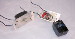
When you feed an electronic bulb, the load is really the bulk storage capacitor. Modern dimmers can handle the inrush to this capacitor, and the bulb will dim according to the lower input voltage from the dimmer. These old dimmers simply failed the triac transistor, open-circuit. A teardown was in order (Fig. 1).
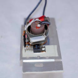
1. This 1980s vintage dimmer switch has no PCB. Assemblers hand-threaded the components leads together and spot-soldered them in place.
A Delightful Discovery
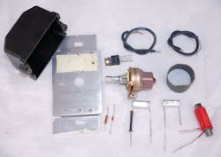
I was astonished and somewhat delighted to see that the dimmer used point-to-point wiring—there was no printed circuit board (PCB) (Fig. 2). If labor is cheap enough, it makes sense to save a few cents on a PCB. I have written about Bob Pease’s famous “airball” prototypes, but here was an airball designed for high-volume production.
2. The dimmer has a simple circuit that required few components. Unfortunately, it cannot operate fluorescent or LED bulbs. It used point-to-point wiring, like old black-and-white Zenith TV sets.
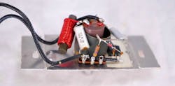
The teardown showed the simplicity of the circuit (Fig. 3). It’s a classic “leading-edge” dimmer circuit. The power path consists of the TO220-packaged triac and a large iron-core inductor. The M8D45 triac is rated 10 A and 200 V. The inductor reduces electromagnetic interference (EMI) caused by the fast switching of the triac.

3. The dimmer is a leading-edge type where an RC network phase-shifts the input signal. That adjustable delayed signal triggers the triac. There’s no need for a neutral connection—the dimmer is wired in series with the load and the incandescent bulb provides the path to neutral. The push-switch is not shown in this schematic.
To trigger the triac, the designers used an RC network to phase-shift the input voltage. The capacitor C2 delays the voltage, a lag in the time domain, equivalent to a pole in the frequency domain. The resistance is formed by a 310-kΩ potentiometer, wired as a rheostat, in series with a 47-kΩ resistor. The pot also has a push-to-actuate switch for the load, not shown in this schematic.
There’s a second capacitor, C1, that the designers put across the inductor and triac to help reduce EMI. The phase-shifted signal feeds the gate of the triac through diac D1, a bidirectional breakdown diode. It acts like back-to-back Zener diodes, with a breakdown of 33 V.
This design is a classic leading-edge dimmer. It works by suppressing the leading edge of the ac power sinusoid. If there’s minimal phase shift, the triac triggers right at the beginning of the sinusoid. If the pot has maximum resistance, it pushes the phase shift out far enough so that most of the sinusoid is suppressed, and the triac only turns on at the very end of the sinusoid, if at all.
A Look at the Switch
The combination switch/potentiometer was sourced from Japan (Fig. 4). The engineers put a cardboard tube around it to prevent short-circuits. It was the primary structure for the airball wiring, along with the triac, which was glued to an insulating sheet mounted to the faceplate of the dimmer switch (Fig. 5).
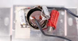
4. A thin cardboard tube surrounds the potentiometer/switch assembly. The fact that one of the capacitor leads is almost shorting the power switch shows the uncontrolled nature of hand assembly.
5. A fiberglass mat served to insulate the triac from the dimmer switch faceplate. The fiberglass and the triac are held in place by white epoxy.
The faceplate served as both a heatsink and a mounting structure (Fig. 6). The potentiometer does not mount with a nut. Instead, the manufacturer bent two metal tabs over into the faceplate. The faceplate also provides a place to rivet on the black Bakelite thermoset plastic housing.
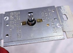
6. The faceplate of the dimmer has the rivets drilled out that hold the black plastic housing. Two thin tabs bend over to secure the potentiometer/switch assembly. The faceplate reads “DO NOT WIRE HOT; TURN OFF POWER,” and “FOR PERMANENTLY INSTALLED INCANDESCENT FIXTURES ONLY.” It also had the 600-W, 120-V rating, and an Underwriters Laboratory (UL) listing mark, as well as the manufacturer: Gemini, Center Valley, PA.
While I admire a design so cheap it does not have a circuit board, there was a lot of labor involved to assemble the dimmer. One interesting touch was that one of the terminals on the potentiometer was bent 90 degrees to allow a capacitor lead to thread through it, and protected by a black tube, to connect to the triac (Fig. 7).
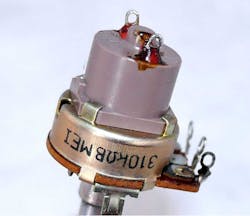
7. The assemblers had to bend one of the terminals of the potentiometer/switch so that they could thread a capacitor lead behind the other terminals. That lead is what feeds input power to the triac.
Double Obsolescence
It’s a shame that this dimmer design is doubly obsolete. It cannot feed an electronic bulb like a compact fluorescent or LED. It also has obsolete assembly technology. There are few places left in the world where labor costs are so low you can have people hand-assemble cheap consumer electronics. Unlike some old electronics, I have no nostalgic thoughts for these dimmers and was glad to put in modern switches in their place.

About the Author

Paul Rako
Creative Director
Paul Rako is a creative director for Rako Studios. After attending GMI (now Kettering University) and the University of Michigan, he worked as an auto engineer in Detroit. He moved to Silicon Valley to start an engineering consulting company. After his share of startups and contract work, he became an apps engineer at National Semiconductor and a marketing maven at Analog Devices and Atmel. He also had a five-year stint at EDN magazine on the analog beat. His interests include politics, philosophy, motorcycles, and making music and videos. He has six Harley Sportsters, a studio full of musical instruments, a complete laboratory, and a video set at Tranquility Base, his home office in Sun City Center Florida.
Comment About the Article
To join the conversation, and become an exclusive member of Electronic Design, create an account today!

Leaders relevant to this article: