Quadrifilar Helix Antenna: Simplifying Remote Communications
What you’ll learn:
- Why there’s a need for a lightweight, easily reconfigured antenna.
- The clever and simple design devised by the researchers.
- Some aspects of performance evaluations in various configurations.
Antennas exist in countless configurations and arrangements, and many can be adjusted to modify their gain, radiation pattern, and other attributes. For example, you can change some characteristics of the widely used Yagi-Uden antenna by varying the number of elements, their spacing, their lengths, and other factors. However, making these changes in passive antennas can be anything from a modest inconvenience to a major hassle, depending on the circumstances.
Recognizing this shortcoming, researchers at Stanford University and the American University of Beirut (AUB) have devised a portable antenna that can be quickly deployed in disaster-prone areas or used to set up communications in underdeveloped regions. Their quadrifilar helix (QFH) antenna squishes down to a small size and can easily shift between two configurations to optimize it for satellites or dispersed devices on the ground—and without using additional power.
Their initial idea was inspired by the way antennas are designed for being deployed in space. Those antennas must be very lightweight and packaged as tightly as possible. Once their vehicle launched and the satellite deployed, they unfold into the proper shape for use. The researchers wanted their antenna to be similarly collapsible and lightweight.
The Ingenious Design Behind the QFH Antenna
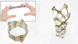
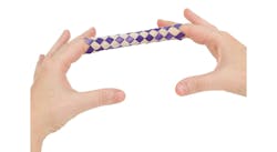
The antenna is made of fiber composites and resembles a child’s finger-trap toy, with multiple strips of material crossing in spirals (Fig. 1).
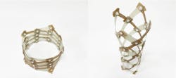
The structure consists of counter-rotating helical strips, connected by rotational joints to allow for a simultaneous change in the helix height and radius. Due to its unique structure, the researchers can adjust the pattern and characteristics of the new antenna by pulling it into a longer or shorter shape configuration (Fig. 2).
At its most compact, the antenna is a hollow ring that stands just over 1 inch tall (2.5 cm), about 5 inches (12.5 cm) across—not much larger than a bracelet—and weighs 1.4 ounces (40 grams) (Fig. 3). In this collapsed shape, the radiation pattern is circularly polarized, unidirectional, and suitable for linking to satellites. In contrast, when stretched out to about a foot tall (30 cm), the antenna has an omnidirectional pattern such as for a Wi-Fi router. These dimensions were chosen to optimize performance around 1.1 to 1.2 GHz within the L-band (1.0 to 1.2 GHz).
Of course, it’s one thing to have a clever insight or idea, but actually implementing and fabricating it is another. Further, in contrast to finger toys, antennas also need a feedline arrangement that minimizes impedance disruptions and VSWR.
Making the transition between collapsed and extended states requires just a simple pull or push. No tools are required, and these actions don’t need to be precise because the structure “snaps” into the right position once the antenna is moved past a certain point.
QFH Antenna Fabrication
All of the helical strips were manufactured from E-glass fiber-reinforced epoxy composites. The conductive strips contain a thin woven phosphor-bronze mesh (292 g/m2) at the midplane of the laminate. Glass fiber-epoxy prepreg with an areal weight of 25 g/m2 is used and laminated to the desired layup, and then it’s cured for two hours at 120°C in an autoclave.
The cured material is cut to size to create the strips. A stencil is employed for drilling holes at the intersection points of the strips, and these are assembled into a helix using nylon screws. To reduce joint friction, Teflon washers are used between the strips. Friction in the joints can affect the stable points and reduce repeatability.
Performance Evaluations of the QFH Antenna
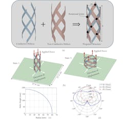
Analysis included mechanical issues including strain and torsional effects (Fig. 4).
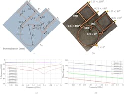
The feed: The four conductive strips of the QFH antenna are fed by a dedicated network that’s fixed underneath the antenna’s ground plane (Fig. 5). The network supplies signals of equal amplitude in sequential quadrature phases. The network relies on one rat-race coupler and two 3-dB hybrid couplers. The rat-race coupler is a reciprocal four-port network that splits the input signal into two equal-output signals with a phase shift of 180 degrees. Two of the output ports of the rat-race coupler connect to two 3-dB hybrid couplers.
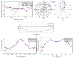
The antenna design was tested and results were compared to simulation predictions, with close agreement (Fig. 6). They also did a deployment demonstration using shape memory-alloy springs that were heated to deploy the antenna remotely.
The project is detailed in their very readable and comprehensive 12-page paper “A multi-stable deployable quadrifilar helix antenna with radiation reconfigurability for disaster-prone areas,” published in Nature Communications. There’s also a nine-page “Supplementary Materials” file and a short video.
About the Author

Bill Schweber
Contributing Editor
Bill Schweber is an electronics engineer who has written three textbooks on electronic communications systems, as well as hundreds of technical articles, opinion columns, and product features. In past roles, he worked as a technical website manager for multiple topic-specific sites for EE Times, as well as both the Executive Editor and Analog Editor at EDN.
At Analog Devices Inc., Bill was in marketing communications (public relations). As a result, he has been on both sides of the technical PR function, presenting company products, stories, and messages to the media and also as the recipient of these.
Prior to the MarCom role at Analog, Bill was associate editor of their respected technical journal and worked in their product marketing and applications engineering groups. Before those roles, he was at Instron Corp., doing hands-on analog- and power-circuit design and systems integration for materials-testing machine controls.
Bill has an MSEE (Univ. of Mass) and BSEE (Columbia Univ.), is a Registered Professional Engineer, and holds an Advanced Class amateur radio license. He has also planned, written, and presented online courses on a variety of engineering topics, including MOSFET basics, ADC selection, and driving LEDs.
