How to Determine ADC/DAC Performance for Digital Control Systems

What you’ll learn:
- How to define the performance criteria of a digital control feedback system, such as a PID control system.
- How to define the speed and resolution of the control DAC and the sense ADC by using the performance of the device under control.
- How to test the device under control for stability and transient step response.
Digital feedback control is widely applied to manage a variety of devices, collectively referred to as devices under control (DUC), such as motors, temperature systems, servo actuators, system pressure regulators, and flow-rate controllers. The goal in digital feedback control design is to determine the performance criteria needed for a sensor’s analog-to-digital converter (ADC) and the controller’s digital-to-analog converter (DAC).
In classical analog controllers (Fig. 1), signals are proportional voltages operated on by op-amp-based circuitry that implements the core control-loop functions, namely, Gain/Multiply, Sum/Addition, Difference/Subtraction, Derivative, and Integral. By comparison, digital controllers perform control computations on digital data streams, with the control math implemented in digital logic hardware or in code running on microcontrollers (MCUs) or programmable logic controllers (PLCs).
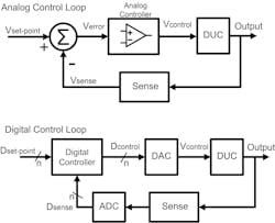
Digital controllers emulate this analog controller behavior through suitable digital hardware and software. They require that ADC and DAC performance be sufficient to capture and manipulate the DUC’s behaviors with adequate time and amplitude resolution.
The Move to Digital Controllers
While many integrated circuits still employ analog feedback for specific applications, such as bias control, voltage regulation, phase-locked loops (PLLs), or automatic gain control (AGC), general embedded and industrial controllers have transitioned to digital implementations for greater flexibility and integration. The concept of digital emulation of analog systems means that the digital system must adequately reproduce analog functions, with ADCs and DACs forming the critical interface between the digital controller and the real world.
In practical industry settings, instead of relying strictly on classical control theory math, most digital controllers employ proportional-integral-derivative (PID) elements, whose tuning is often performed empirically. MCUs and PLCs can often handle complete digital PID implementations internally, making them cost-effective, efficient, and easily tuned via software parameter changes.
A few critical factors must be considered in digital control design:
- System required DUC output accuracy
- DAC resolution, clocking rate, and ripple performance are needed
- Sensor accuracy, ADC resolution, and sampling rate
- Digital math accuracy
While the first pair of considerations apply to both analog and digital systems, the specific performance of the ADC and DAC is especially significant in digital implementations. Sensor accuracy should exceed the required DUC output accuracy, and the control algorithm’s computational precision should surpass the DAC performance to avoid introducing new errors.
>>Download the PDF of this article

A continuous-time DUC signal (Fig. 2) is sampled in time and quantized in amplitude by the ADC, generating a digital data stream input to the digital controller. The sampling rate and resolution of the ADC will consequently constrain the precision with which the DUC can be sensed and controlled. Estimating an appropriate ADC sampling rate often involves examining the DUC’s time-domain step response — the finer the ADC’s amplitude resolution and the more samples per unit time, the finer the control achievable by the digital system.

DUC Test Setup
The stability of a DUC is a key property in control system design. A feedback control loop improves DUC stability, but only within its bandwidth. High-frequency variations in the DUC that exceed the control system’s bandwidth remain uncompensated.
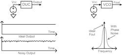
Figure 3 illustrates the testing setup where a fixed input, in a stable environment without disturbances (e.g., load or temperature variations), should produce a fixed DUC output. An example is a voltage-controlled oscillator (VCO). Even with a stable analog input, intrinsic phase noise and frequency jitter can cause output frequency variation.
A DUC’s DC transfer function, which is the relationship between input (e.g., voltage) and output (e.g., frequency), determines the required DAC resolution (Fig. 4). By mapping the system’s required min-max output accuracy to corresponding min-max DAC input values, one can define the minimum step size (least significant bit, or LSB) needed from the DAC. For robust design, it’s recommended to have eight or more DAC LSB steps within the required accuracy window.

A test setup (Case A) inputs a series of voltage steps to the DUC and the output frequency is measured. The input should come from a low-noise DC source power to fully isolate and test just the DUC performance. If the initial resolution falls short (as in Case B), adding additional DAC bits improves performance, as shown in Case C of Figure 4.
Design margin arises if multiple DAC LSB steps are contained within the system’s accuracy range, protecting the design from small errors or drift. However, if the DAC resolution isn’t sufficient, the control system may not achieve the desired DUC accuracy in closed-loop operation.
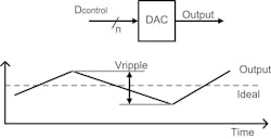
As Figure 5 shows, for a fixed digital input, the DAC output should ideally be stable. Some DACs, especially those using pulse-width modulation (PWM), produce ripple, making LSB resolution irrelevant if output variance exceeds the granularity of the DAC’s LSB.
The ADC’s Role
The ADC’s purpose is to digitize the DUC’s sense circuit output with resolution, repeatability, and accuracy that surpasses the system’s overall accuracy requirement. Using the same method as for the DAC, the ADC resolution is set to be finer than the desired DUC output resolution.
Determining the ADC’s sampling rate requires careful attention. While control engineering textbooks can relate the ADC sample rate to the control loop’s bandwidth, in practice it’s effective to reference the DUC’s step response (Fig. 6).

The open-loop step response, reflecting the DUC’s reaction to a sudden input change, reveals key time constants (process time, Tprocess). Setting a sample period (Tsample) to collect at least 10 samples during Tprocess is a practical guideline. This ensures the controller accurately perceives system dynamics and can react appropriately.
Applying a step input at the DUC’s midpoint operating range ensures a meaningful characterization. For instance, for a 0- to 1-V DUC input, applying a step from 450 mV to 550 mV avoids nonlinearities found at the extremes.
Once the minimum bit-depth and sampling rate for the ADC are determined, an appropriate converter can be selected, aiming for equal or better performance than the calculated requirements. The selected ADC’s maximum sampling rate then defines the loop’s operating rate. A corresponding DAC with matched or better resolution and speed can then be chosen to support the output side.
These methods allow designers to specify ADC and DAC performance in digital control loops, supporting a wide array of possible control algorithms — from PID to more sophisticated or custom approaches. More extensive details on control theory, tuning, sensor interfaces, and hardware circuits for embedded applications can be found in comprehensive texts on applied embedded electronics, including this author’s book, Applied Embedded Electronics – Design Essentials for Robust Systems.

Reference
Applied Embedded Electronics - Design Essentials for Robust Systems, Jerry Twomey, 2023, ISBN 978-1-098-14479-1, O’Reilly Media.
>>Download the PDF of this article
About the Author

Jerry Twomey
Founder and Engineering Consultant, Effective Electrons
Jerry Twomey has extensive experience designing electronics for medical devices, electromechanical systems, and transistor-level integrated circuits. This includes many consumer, medical, aerospace, and commercial products.
Jerry holds several patents and is an author of multiple trade magazine publications, many of which appeared in Electronic Design magazine, providing solutions for commonly encountered design problems. He teaches seminars in embedded systems, IC design, EMC, and medical technology, and has lectured at UCSD. Jerry has also chaired the San Diego IEEE chapters for Microwaves and for Solid State Circuits.
Jerry Twomey is the author of Applied Embedded Electronics – Design Essentials for Robust Systems, a comprehensive reference book covering the design process for embedded-systems electronics from initial concept to final PCB.
Comment About the Article
To join the conversation, and become an exclusive member of Electronic Design, create an account today!

Leaders relevant to this article: