Derating Guidelines for Tantalum Capacitors: How to Boost Reliability and Performance

Capacitor dielectrics come in various types, each with unique features suited for specific applications. Advances in materials and manufacturing have increased the capacitance and voltage capabilities of these dielectrics, suiting them for a wider array of applications and sometimes replacing other device families due to circuit requirements.
Significant technical developments often aim to address specific needs or minimize limitations in particular applications. Solid and wet tantalum capacitors are known for their excellent energy density and reliability, with wet tantalum performing well at higher temperatures. However, their utilization is often limited by specifications, operating requirements, and cost.
The development of tantalum polymer capacitors, which require much lower voltage derating, has expanded their usable capacitance and voltage capability, resulting in fewer capacitors needed or a smaller footprint. As a result, tantalum polymer capacitors are increasingly becoming the best solution for many applications. This article compares the derating differences among the three tantalum dielectrics.
Comparing Solid Tantalum and Polymer Tantalum Capacitors
Performance and reliability are the foundation for any equipment. Understanding usage conditions and the reasons for derating capacitors simplifies your decision-making when comparing capacitor technologies.
Manufacturers design and test tantalum capacitors to ensure only high-quality parts reach the market. However, PCB assembly processes can thermally stress the devices, potentially lowering their breakdown threshold in the future. This stress typically affects the device during power-on or transient events, but once self-healing occurs, short transients and power-on should not impact long-term reliability.
Operating solid tantalum capacitors at or above their rated voltage (RV) can lead to damage and catastrophic failure, making voltage derating crucial for device reliability. Reliability is often expressed as a percentage of failure per 1,000 hours of operation. Tantalum capacitors used near their RV usually have a 0.1% to 1% failure rate per 1,000 hours. Most failures occur during power-on events, which are not included in the operating failure-rate calculation.
When considering an application, the basic failure rate (FB) must be adjusted for specific operating conditions using correction factors from the EIA handbook for reduced voltage (FU), lower temperature (FT), and series resistance (FR). Lower values for these factors can significantly reduce failure rates.
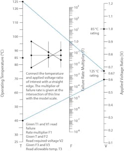
You can use a graphical calculator like the one shown in Figure 1 to evaluate the impact of each correction factor based on conditions. For example, at 40°C and 60 % of the RV, the failure-rate correction factor is about 0.00001.
Commercial solid tantalum capacitors have a standard failure rate of 1 % per 1,000 hours ("M-level"). For high reliability applications, the MIL-STD-217 standard was established, which includes a 50% voltage derating to achieve a 5 to 15 failures in time (FIT) rate, where 1 FIT equals one failure per billion hours.
Understanding the Voltage Acceleration Factor and Its Impact on Capacitor Reliability
The voltage acceleration factor (VAF) is crucial for designing reliable capacitors, as it helps you quantify how voltage and temperature affect their failure rates (see Equation below). The MIL-HDBK-217F Notice 2 handbook provides you with guidelines for calculating the basic FIT and adjusting it based on various factors.
As the temperature and applied voltage increase, the FIT can rise dramatically. For example, at 125°C, the FIT increases fivefold, and with 100% RV, it can exceed 5,000. This exponential increase highlights the importance of proper derating to maintain reliability. By understanding and applying the VAF, engineers can predict and enhance the lifespan and performance of capacitors, ensuring their suitability for various applications.
While temperature impacts the FIT by a factor of 5, voltage has a much more significant effect, with an exponential factor of 17. Once you exceed 60% RV, the factor doubles and rapidly increases: 14.7 at 70%, 134 at 80%, and much higher beyond that. Therefore, the VAF dramatically influences the FIT, especially when the derating factor (S) is above 60 %.
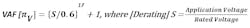
Figure 2, taken from the military handbook, shows the effect of temperature on FIT with four curves for the RV effect.
Follow Voltage, Temperature, and Impedance Guidelines to Improve Component Reliability
Improving component reliability is crucial to your product development, leading to the creation of established, exponential failure-rated parts. These parts undergo life tests at elevated temperatures to predict overall reliability using an exponential model. The levels of reliability include “P” (0.1%), “R” (0.01%), and “S” (0.001%).
Weibull voltage grading is another reliability standard for solid tantalum capacitors, aiming to screen out infant mortality units, eliminate lot variability, and remove uncharacteristic lots. The levels are B (0.1% per 1,000 h), C (0.01% per 1,000 h), and D (0.001% per 1,000 h).
>>Download the PDF of this article, and check out the TechXchange for similar articles and videos
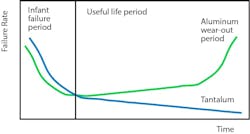
Solid tantalum capacitors (molded, conformal, and hermetically sealed) can last indefinitely if used within voltage, temperature, and impedance guidelines, as there's no dielectric wear-out under derated conditions. Failures typically occur early, such as at first turn-on, and decrease over time.
While factors like temperature, circuit impedance, ripple current, and mechanical stress affect reliability, applied voltage is the most critical. Derating the voltage enhances long-term reliability and initial power-on performance. In contrast, aluminum electrolytic capacitors exhibit a "bathtub" effect, where end-of-life failures eventually increase, unlike the more consistent reliability of solid tantalum capacitors (Fig. 3).
Due to the impact of voltage derating, all tantalum capacitor manufacturers publish derating guidelines for their parts. Vishay uses the EIA-809 standard as well as the NASA and MIL-STD guidelines to dictate the recommendations shown in Figure 4. Usually, the application (working) voltage should be between 0.5 and 0.6 V of the RV. For RV ≥ 35 V, Vishay recommends an even higher derating ratio, with a minimum of 50% derating.
4. Vishay uses the EIA-809 standard as well as the NASA and MIL-STD guidelines to dictate the recommendations in the table for Recommended Voltage Derating Guidelines below 85°C.
When conductive polymer tantalum capacitors were invented, the primary feature of the new cathode system was a much lower equivalent series resistance (ESR) than existing MnO2 devices. This was because the conductivity of polymer is orders of magnitude better than MnO2. In addition to the significantly lower ESR, it was found that a conductive polymer cathode also features more robust performance under voltage stress.
Handling the Heat: Solid vs. Polymer Tantalum
Both types of tantalum capacitors have a self-healing mechanism, but it’s technologically different for solid- and polymer-type capacitors. Solid tantalum capacitors, as the formula for the cathode (MnO2) suggests, have an oxygen source inside the device. In the event of elevated leakage current, the current flows through the dielectric flaw and generates localized heat, increasing the temperature in the vicinity of the potential failure location.
This elevated temperature causes a reduction of the MnO2 to a lower order (Mn2O3), which has a resistance that’s orders of magnitude higher than the original MnO2. The potential failure site then becomes electrically isolated and the current flow decreases to an acceptable level. The oxygen released in the conversion from MnO2 to Mn2O3 is consumed by the tantalum pentoxide dielectric.
However, it’s possible that if the temperature rise is uncontrolled or occurs too quickly, a dangerous ignition event can be triggered.
By comparison, for polymer tantalum capacitors, the localized heating of the potential failure site causes the polymer to become non-conductive, insulating the spot and reducing the leakage current — a significantly safer outcome. The capacitors will fail short, but it’s considered benign because the parts will not burn when failing, allowing for more generous derating guidelines:
- 90 % for products rated up to 10 V
- 80 % for products higher than 10 V
Polymer tantalum has recently been provided a MIL-STD, MIL-PRF-32700, to guide users. The failure rates are defined differently to those of MnO2 tantalum, as a polymer device has better lifetime performance. They can’t be Weibull graded as we do with MnO2, because the capacitors don’t fail under the Weibull criteria.
To better understand the failure rates, HALT (highly accelerated life test) testing is used to establish failure rates. The change in material set and production techniques from MnO2 manufacturing creates this difference in behavior, significantly reducing voltage derating recommendations. Figure 5 shows the derating recommendations as specified in MIL-PRF-32700.
5. This table shows the derating recommendations voltages (V DC) for polymer tantalum specified in MIL-PRF-32700.
When you compare these two types of tantalum capacitors, you'll see that, when used correctly within derated voltage and temperature conditions, both can provide a very long lifetime.
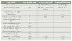
For example, a life test of 100 samples for 1,000 hours at the specified temperature and RV predicts an FR of 2.3 % per 1,000 h (Fig. 6). Even if there were no failures (m = 0), this FR would be unacceptable in most applications. By derating MnO2 capacitors by 50% and polymer capacitors by 20%, you can bring the predicted FR to approximately 0.1% and increase the mean time to failure (MTTF) from five years to over 100 years.
Voltage derating has two specific objectives. Initially, to avoid failure post-board mount and at first power-on, and then for dielectric breakdown under temperature/voltage stress. It’s important to distinguish between FR and turn-on/surge events.
As mentioned earlier, the ability of tantalum capacitors to self-heal means not all events lead to device failure and decreasing FR is typically based on steady-state conditions. Transient/surge events can occur at any time and the high stress may cause failures that aren’t preventable by the self-healing feature.
Wet Tantalum Capacitor Derating Requirements
Wet tantalum capacitors are a completely different technology that has a liquid rather than solid cathode. This electrolyte provides true self-healing and no contact stresses on the dielectric. Due to their high reliability and long life, they have been widely used in harsh environment applications for many years.
These capacitor types have established reliability with 10,000 h life and are designed to be hermetic, so there are no environmental concerns aside from temperature and shock/vibration. The majority of the initial construction steps are the same as the two solid cathode types.
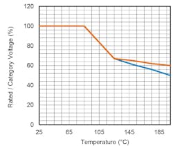
For wet tantalum devices, the maximum working voltage is equal to the RV if they operate in the temperature range of −55 to +85°C. Above 85°C, it decreases linearly to 2/3 × RV at the maximum working temperature of +125°C. For Vishay series with higher maximum operating temperatures — like the 134D, 135D, T11, T24, and T34 — it will go to 0.5 × RV at extreme temperatures. Above +85°C, it’s common to refer to the maximum working voltage as the category voltage. Figure 7 illustrates the ratio between the RV and category voltage.
While most wet tantalum capacitor series don’t require voltage derating when used at or below +85°C, you should select the DC working voltage (bias) so that the sum of the DC bias and AC (ripple) voltages doesn’t exceed the RV. For increased reliability, it’s recommended to have a 10% to 20% guard band, meaning not to exceed 80% to 90% of the RV at or below +85°C. At higher temperatures, maintain the same ratio relative to the category voltage.
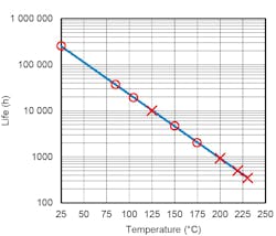
Extensive historical data has been collected, showing 10,000 h of life at RV for +85°C. Additional data is available for 10,000 h at the +125°C derated voltage, as well as for high temperature operations at +200°C and even +230°C. By adding a few more data points and using the Excel FIT curve calculator, we can now reliably predict lifespan at intermediate temperatures along the curve. This allows for accurate estimates of life expectancy within the high-temperature operational range (Fig. 8).
For the highest levels of reliability, mostly space applications, NASA has its own derating rules for capacitors (Fig. 9). Note that polymer isn’t included at this time. Also, tantalum foil is no longer manufactured. We can see that NASA has mandated a minimum of 50 % derating on solids up to 70 °C, not 85 °C. Above this, further derating is needed. This is similar to what is required of wets.
9. NASA derating rules for various capacitor types, listing corresponding military styles, voltage derating factors, and maximum ambient temperature limits to guide component selection in space-grade applications.
Conclusion
Derating requirements differ significantly among the three major tantalum capacitor types due to their different cathode systems. Voltage derating provides the greatest improvement in long-term reliability and initial power-on performance. Understanding these differences will help ensure optimal reliability: MnO2 capacitors require 50% derating, polymer capacitors 20%, and while wet tantalum capacitors don't technically need it, a 10% to 20% derating is recommended.
These differences lead to significant advantages in board area size, weight, and manufacturing costs when comparing electrical performance and selecting tantalum capacitors.
>>Download the PDF of this article, and check out the TechXchange for similar articles and videos
About the Author
Jon Rhan
Senior Manager Product Marketing - Tantalum, Vishay Intertechnology Inc.
Jon Rhan is Senior Manager Product Marketing - Tantalum at Vishay Intertechnology Inc. Holding MBA/BSEE degrees, he has extensive global experience in leading cross-functional teams from engineering, product management, operations and customer support. Jon has designed and implemented policies and procedures with respect to design engineering, product development, manufacturing operations and planning, production and scheduling, infrastructure development, quality and reliability regimens, and new business ventures.
Comment About the Article
To join the conversation, and become an exclusive member of Electronic Design, create an account today!

Leaders relevant to this article: