Wait... There’s Yet Another “Even Better” Op Amp?
What you’ll learn:
- How every op amp is different and why so many unique models are available.
- The attributes of the Analog Devices MAX74810 dual op amp.
- What resources are available to support design-in using this component?
There’s a conundrum in analog circuitry facing designers who are selecting and using op amps. On one side, the op amp is a functionally simple block that can be adapted to countless roles with appropriate peripheral circuitry, including basic passive devices. On the other, this apparently simple block is characterized by many unique parameters, and it’s their values that determines if the selected op amp will be a suitable choice for the intended role.
That’s why op amp vendors keep introducing new versions. Even if they offer only a modest improvement in one or several specifications compared to what’s already out there, the difference may enable users to significantly improve system performance or simplify design, such as by eliminating the need for calibration or trims.
ADI’s New Dual-Channel, Zero-Drift Op Amp
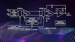
One such device to recently arrive is Analog Devices' MAX74810, a chopper-stabilized, dual-channel, zero-drift op amp with low noise and power, ground-sensing inputs, and rail-to-rail outputs (Fig. 1). It’s optimized for total accuracy over time, temperature, and voltage conditions.
The wide operating voltage and temperature ranges, as well as the high open-loop gain and very low DC and AC errors, make this device suitable for amplifying very small input signals and for accurately reproducing larger signals in a wide variety of applications. Representative apps include inductance, capacitance, and resistance (LCR) meter/megohmmeter front-end amplifiers; load cell and bridge transducers; magnetic force-balance scales; high-precision shunt-current sensing; and thermocouple/resistance temperature detector (RTD) sensors.
>>Check out this TechXchange for similar articles and videos
Components such as op amps aren’t characterized primarily by their many internal functions, since they really only have an input, core function, and an output. Instead, it’s the list of subtle yet critical specifications that defines the specific model. For the MA74810, these include:
- Low offset voltage: 7 μV (maximum)
- Extremely low offset voltage drift: 30 nV/°C (maximum)
- Low-voltage noise density: 5.8 nV/√Hz (typical)
- 117-nV p-p noise (typical) from 0.1 to 10 Hz
- Low input bias current: 50 pA (typical)
- Gain-bandwidth product: 2.7 MHz
- Single-supply operation: input voltage range, includes ground and rail-to-rail output
- Unity-gain stable
The op amp supports a wide range of operating voltages, offering single-supply operation of 4.5 to 50 V and dual-supply operation from ±2.25 to ±25 V. This makes it a good choice for applications using single-ended supplies of 5, 10, 12, and 30 V, or for applications using higher single supplies and dual supplies of ±2.5, ±5, and ±15 V. (Yes, there are still many analog-designs situations where higher voltage is either preferred or mandated by system and sensor realities.)
Protective Measures
The MAX74810 also has on-chip filtering to achieve high immunity to electromagnetic interference (EMI) via internal ESD protection diodes (D1, D2, D3, and D4) connected between the inputs and each supply rail (Fig. 2).
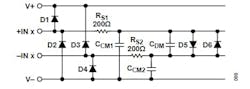
These diodes protect the input transistors in the event of electrostatic discharge and are reverse-biased during normal operation. This protection scheme allows voltages as high as approximately 300 mV beyond the rails to be applied at the input of either terminal without causing permanent damage.
The EMI filter RC networks set the −3-dB low-pass cutoff frequencies at 50 MHz for common-mode signals, and at 33 MHz for differential signals. After the EMI filter, back-to-back diodes (D5 and D6) are added to protect internal circuit devices from high-voltage-input transients.
The MAX74810, which is fully specified over the extended industrial temperature range of −40 to +125°C, is housed in an 8-lead MSOP package. The 23-page datasheet includes the many graphs and tables designers need for op amp assessment and error budgeting.
While an evaluation board pre-loaded with connectors and components doesn’t make sense for a flexible device such as this dual op amp, designers may want to check it out in an actual circuit configuration. For this reason, Analog Devices offers the EVAL-PRAOPAMP-2RMZ Dual Universal Precision Op Amp Evaluation Board, a bare board with pads and lands that provides extensive flexibility for different application circuits and configurations (Fig. 3).
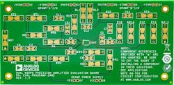
This board isn’t intended for use with high-frequency components or high-speed amplifiers. However, it does offer the user many combinations of various circuit types, including active filters, instrumentation amplifiers, composite amplifiers, and external frequency-compensation circuits. Several examples of application circuits are provided in the associated eight-page Application Note AN-763.
>>Check out this TechXchange for similar articles and videos
About the Author

Bill Schweber
Contributing Editor
Bill Schweber is an electronics engineer who has written three textbooks on electronic communications systems, as well as hundreds of technical articles, opinion columns, and product features. In past roles, he worked as a technical website manager for multiple topic-specific sites for EE Times, as well as both the Executive Editor and Analog Editor at EDN.
At Analog Devices Inc., Bill was in marketing communications (public relations). As a result, he has been on both sides of the technical PR function, presenting company products, stories, and messages to the media and also as the recipient of these.
Prior to the MarCom role at Analog, Bill was associate editor of their respected technical journal and worked in their product marketing and applications engineering groups. Before those roles, he was at Instron Corp., doing hands-on analog- and power-circuit design and systems integration for materials-testing machine controls.
Bill has an MSEE (Univ. of Mass) and BSEE (Columbia Univ.), is a Registered Professional Engineer, and holds an Advanced Class amateur radio license. He has also planned, written, and presented online courses on a variety of engineering topics, including MOSFET basics, ADC selection, and driving LEDs.
Comment About the Article
To join the conversation, and become an exclusive member of Electronic Design, create an account today!

Leaders relevant to this article: