Calculating Temperature Coefficient in Precision Analog Circuits
What you'll learn:
- A look at a simple analytical method for evaluating temperature coefficient in common analog building blocks.
- Identifying additive and multiplicative categories.

Precision analog circuits rarely operate in ideal, temperature-invariant environments. That tends to be a problem because temperature variation is one of the most persistent sources of error for these circuits. Transistor junction voltages, resistor values, and carrier mobility all vary with temperature, resulting in drift of voltage references, bias currents, offsets, and gains. In many applications, such as data converters, sensors, and power-management systems, temperature drift directly limits achievable accuracy.
While temperature effects are well understood at the device level, system-level temperature-coefficient (tempco) analysis often becomes complicated due to nonlinear dependencies and mixed circuit behaviors. Although modern simulation tools provide temperature sweeps, it pays for engineers to answer a couple of fundamental questions during the design process:
- Which parameters or devices dominate temperature drift?
- How does circuit topology amplify or suppress these effects?
This article presents a simple analytical method for evaluating temperature coefficient in common analog building blocks. By classifying circuit behavior into additive and multiplicative categories, designers can rapidly estimate temperature sensitivity, identify dominant contributors, and apply effective compensation techniques early in the design cycle.
The Difference Between Absolute and Relative Temperature Coefficient
Before analyzing circuits, it’s important to distinguish between two commonly used forms of temperature coefficient.
The absolute temperature coefficient (ATC) measures how an output quantity changes directly with temperature:

Typical units include mV/°C, µA/°C, or Ω/°C. ATC is most useful when absolute error matters, such as voltage-reference drift.
The relative temperature coefficient (RTC) normalizes the drift to the nominal value:

It’s usually expressed in ppm/°C or %/°C and is particularly suitable for circuits in which the absolute output value is adjustable, such as adjustable-output (VOUT) regulator circuits.
The Categories of Circuit Temperature Behavior
Most analog circuits can be reduced to one of two functional categories for temperature analysis. The first category — additive or subtractive functions — take the form:

A bandgap voltage reference is one of the most common examples:

where:
- VBE is complementary-to-absolute temperature (CTAT)
- ΔVBE is proportional-to-absolute temperature (PTAT)
When it comes to calculating the temperature coefficient, the rule for additive functions is as follows:

The key insight is that ATC can be added algebraically. If one term has a significantly larger temperature coefficient than the others, it dominates the overall drift.
Ultimately, temperature independence is achieved by canceling positive ATC terms with negative ATC terms. This principle is fundamental to bandgap references and many compensated bias generators.
The second category — multiplicative or ratio functions — takes the form:

One of the most common examples is a current reference based on a voltage-to-resistor ratio:

The rule when calculating the temperature coefficient is to apply first-order differentiation:

where the sign depends on multiplication or division.
The takeaway is that RTC terms can be added algebraically. For multiplicative circuits, temperature drift is minimized by canceling positive RTC terms with negative RTC terms.
For ratio-based circuits, temperature drift is minimized by matching the RTCs of the numerator and denominator in both magnitude and polarity.
Applying the Method: A Reference Current Example
Consider a simple reference current generator circuit as seen in the figure below.
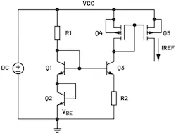

with:
- VBE ≈ −2 mV/°C (CTAT)
- RTCR2 = +100 ppm/°C
As a result, the RTC of the current reference becomes:

For example, with VBE ≈ 0.7 V, the RTC due to VBE can be approximated as follows:

By applying Equation 11 and RTCR2 to Equation 10:

Based on Equation 12, IREF exhibits a strong negative temperature dependence.
Selecting a resistor with an RTC comparable in magnitude and polarity to the numerator’s RTC can significantly reduce overall temperature drift.
Predicting Temperature Performance Before Simulation
This approach works for several reasons. First, the first-order temperature effects dominate over most operating ranges. Second, higher-order nonlinearities are typically small compared to first-order effects and are often negligible in applications that don’t require very high precision. Next, the analysis directly reflects the combined behavior of circuit elements. Most importantly, however, it allows designers to predict temperature performance before simulation or silicon validation.
Ultimately, engineers will want to use ATC when analyzing circuits with additive or subtractive behavior and RTC when analyzing multiplicative or ratio-based circuits.
Temperature-coefficient analysis needn’t be complex to be effective. By classifying circuits into additive and multiplicative categories and applying simple mathematical calculations, engineers can gain rapid insight into temperature behavior. This method bridges the gap between device characteristics and practical circuit design, enabling faster convergence to stable, temperature-robust solutions.
>>Download the PDF of this article
 dreamstime_mikhaildudarev_7261446
About the Author
Sherwin Clemente
Analog IC Design Engineer, Analog Devices Inc.
Sherwin Clemente is an analog IC design engineer in the Industrial, Power, and Precision Group, handling safe power protection products at Analog Devices Philippines. He joined ADI in September 2019. Prior to joining ADI, he worked for four years as a design and development engineer focusing on high-voltage switching regulators. He holds a bachelor’s degree in electronics engineering from the University of La Salette.
Comment About the Article
To join the conversation, and become an exclusive member of Electronic Design, create an account today!
 Leaders Logo
Leaders relevant to this article: