What’s All This T-Coil Stuff, Anyhow? (.PDF Download)

A T-coil is a special form of an inductive peaking circuit that will extend an amplifier’s bandwidth and speed up the output signal rise-time. The circuit uses a coupled inductor and a small bridging capacitor (Fig. 1). A T-coil can double the bandwidth of an amplifier. You can think of the inductor as steering input current into the capacitive part of the load, so it charges up more rapidly. The small bridging capacitor ensures that the input impedance of the T-coil is constant and resistive.
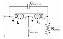
1. A T-coil uses a coupled inductor, essentially a transformer with three leads. It can double amplifier bandwidth, and the bridging capacitor gives it a constant input impedance. The CLOAD might be an input impedance or the capacitance of an ESD diode in a SerDes chip. The RLOAD might be a transmission line or impedance-matching resistor.
