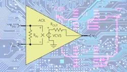
What’s All This Unused Input Stuff, Anyhow?
Digital engineers learned long ago that they should not leave unused inputs unconnected. CMOS chip inputs might float up to some midpoint voltage and turn on the output stage, but that would have a minimal effect on current consumption. The real problem was the output might switch, which would couple to the floating input to switch in the other direction. This would set up an oscillation, greatly increasing power consumption as well as introducing an unwanted noise source.
TTL logic inputs were not supposed to be connected to a power rail directly—you’re supposed to pull it up with a resistor to limit any input current. Many of us “cheated” and just nailed the inputs to VCC. If you looked at the equivalent schematic of the logic chip, you could infer if you can get away with this.
Don’t Do This
The tendency to connect inputs to power or ground made some engineers feel that was the way to deal with unused op-amp inputs (Fig. 1). This is a serious mistake. Connecting both inputs of an operational amplifier together just means that the offset voltage will determine if the output is hard-driven to the positive or negative rail. The offset voltage of a particular part will determine which rail the output goes to, independent of where you tied the inputs.
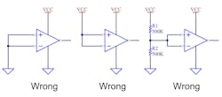
When an output is hard-driven, there’s no feedback that “closes the loop” and stops supplying drive current to the output transistors. Most bipolar op amps have base-current clamping circuits that will limit this current so it doesn’t burn up the chip. CMOS amplifiers will also draw more current when the output is hard-driven, and it’s never good to put any transistor inside an integrated circuit into saturation.
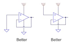
The right thing to do is connect the amplifier as a voltage follower, with the − pin connected to the output pin (Fig. 2). But you can’t always just take the + input to a power rail—it might cause the same problem. You have to ensure the positive input is connected to a voltage inside the input common-mode range. Even that might not be enough if you don’t understand the input section of the amplifier.
Bob Pease Observations
This issue of unconnected inputs was driven home by a communication back in 2007 between analog guru Bob Pease and Dennis Monticelli, the chief technical officer of National Semiconductor at the time. Monticelli noted, “The problem arises when the two inputs are tied together and then pinned somewhere, such as ground. The output state then becomes indeterminate.”
Pease replied, “Well, we agree that that is almost never the right solution for unused inputs. If Vos was one way, the output could still do something stupid. If the Vos is the other way, and you test it, it might seem to be fine— but another part might go bad, and get hot. Right?”
Monticelli commented, “It used to be standard practice to connect the unused op amp as a follower with the + input tied to any convenient system bias voltage that happens to fall within the common mode range.”
Pease replied, “Yeah, but if the CM range includes ground, or −Vs, and you short the + input to that rail, the power supply drain current and heating can still go wild, for some amplifiers.”
Monticelli thought, “Not if you connect it as a follower and keep the inputs within the CM range.”
But Pease said, “NSC does sell at least one quad op-amp where if you connect it as a follower, and tie the + input to the − rail (which is inside its legal range), it pulls a lot of power and gets hot. I'll have to ask Paul Rako what it is. He was surprised to learn this. We agreed, this is a mistake. Maybe we can learn a strategy to keep it from overheating and pulling the battery down.”
An Oddball Part Story
If I remember right, that part was the LMH6584. It was not designed as a general-purpose op amp. It was meant to be a VCOM driver. This is an amplifier that holds the common terminal of an LCD panel at the midpoint voltage, often 6 V in a 12-V panel. The row and column drivers then ac-drive the LCD pixels between 0 V and 12 V. You can’t just use a 6-V power supply, since the VCOM terminal needs extraordinarily fast transient response so that the LCD can be refreshed at 60 Hz or faster. Because VCOM driver amplifiers have very fast slew rates, they can supply the pulse of current needed to fight the capacitive coupling between the pixel terminals of the panel and the large common terminal.
When I connected the part as a follower and connected the + input to ground, the chip current went way up. If you connected all four parts in the quad package like this, it would burn up the chip. Thing is, the part was never meant as a general-purpose op amp, so in the early datasheets, I made clear this was not a quad op amp. But, marketing people have goals and it’s great to say your group released an op amp, not just a specialized LCD part. Pease and I warned that might happen, and sure enough, after a year or two, the title of the datasheet said the part was an op amp.
When I asked the IC designer why the part took so much current when the + input was connected to a rail, he said that, “I removed the base clamps.” When I asked why, he said, “Because the part would oscillate with them in there.” Now before you criticize him, realize he was not tasked with designing a general-purpose op amp, but rather an LCD panel VCOM driver. There was never an unused part in the package, so this would never happen.
As an apps guy that knew the part might be sold as an op amp, I made sure to include a caveat in the datasheet: “It should be noted that if the outputs are driven to the rail and the part can no longer maintain the feedback loop, the internal circuitry will deliver large base currents into the huge output transistors, trying to get the outputs to get past the saturation voltage. The base currents will approach 16 milliamperes and this will appear as an increase in power supply current. Operating at this power dissipation level for extended periods will damage the part, especially in the higher thermal resistance TSSOP package. Because of this phenomenon, unused parts should not have the inputs strapped to either rail, but should have the inputs biased at the midpoint or at least a diode drop (0.6V) within the rails.”
Rail-To-Rail Caveats
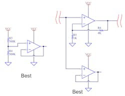
Even rail-to-rail input amplifiers may draw excess current when you connect the + input to one of the power rails. So, as Pease noted, even when you connect as a voltage follower, you’re best off with putting two resistors as a ladder and connect the + pin to the midpoint, to ensure the common-mode input range is at its middle and the op amp can close the loop for the voltage follower (Fig. 3).
If you want to connect the + input to a rail to save the cost or power drain of two resistors, then you have to really understand the input section of the amplifier. Monticelli remarked, “Have customers forgotten this standard practice? Have we forgotten to teach them?” To which Pease replied, “Yes and yes. We gotta put in a little effort to teach them, which we have not done.”
Now if you can ensure the input differential pair is happily in its operating range, you might get away with nailing the positive input to a rail, but be sure the input offset spec is tight enough that the common-mode range is always within range. Pease said, “None of this is necessarily the lowest power drain, unless you get lucky. At least the old LM324 was fairly simple to peg into a low-power state. Bipolar transistors are, alas, more repeatable on this, right? Except, not always.”
I’ve had situations where I did not have the space or budget to include a voltage ladder for unused inputs. In that case I tried to find a voltage or signal somewhere in the circuit that never got too close to the rails, and then just tied the + input to that. Often, it was easiest to just tie that input to another input in the same package. The output would swing, but not being connected to a load, it had a minimal effect on power consumption.
Include Pads or Vias
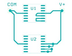
While talking about unused amplifiers, always be sure to show them on your schematic. Also be sure to add some pads or vias to the inputs and outputs so that you can jump it into the circuit should you need an additional amplifier for something (Fig. 4). That’s why you should not route the voltage-follower connection between minus and output under the part. It makes it hard to cut the trace if you have to cobble in another amplifier.
There have been times I needed an inverted digital signal. Setting up a spare op amp as an inverter did the trick, at least until the next spin of the printed circuit board (PCB).